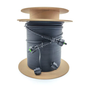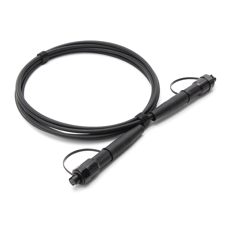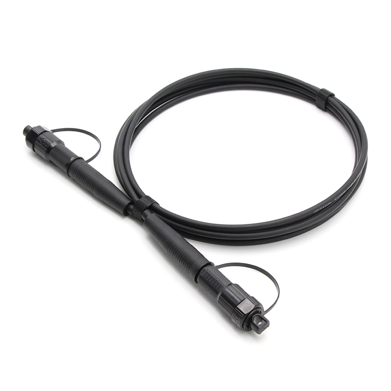



1. Key features
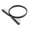
- Fast deployment, plug and play: the preconnectorized design eliminates field splicing and simplifies installation procedures;
- Low-insertion-loss MPO technology for stable optical performance;
- All-dielectric non-metallic round cable: light weight and excellent pull-resistant performance;
- High long-term reliability in extreme environments, with resistance to UV aging and acid-base salt corrosion;
- Waterproof rating meets IP68 requirements;
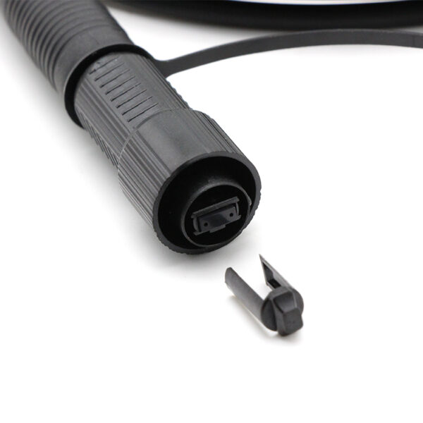
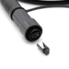
- The connector is fixed by rotation and locking, making installation and removal easy;
- Anti-pull force up to 300 N, effectively ensuring the quality of optical cable construction.
2. Technical Specifications
Optical performance (per mated pair, after cleaning)
| Parameter | Typical | Maximum |
| Insertion loss @ 1310 / 1550 nm | ≤ 0.35 dB | ≤ 0.50 dB |
| Return loss (APC) | ≥ 60 dB | — |
| Test wavelength | 1310 nm / 1550 nm | — |
3. Product Construction
3.1 Connector Assembly
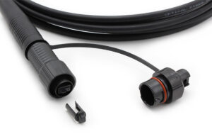
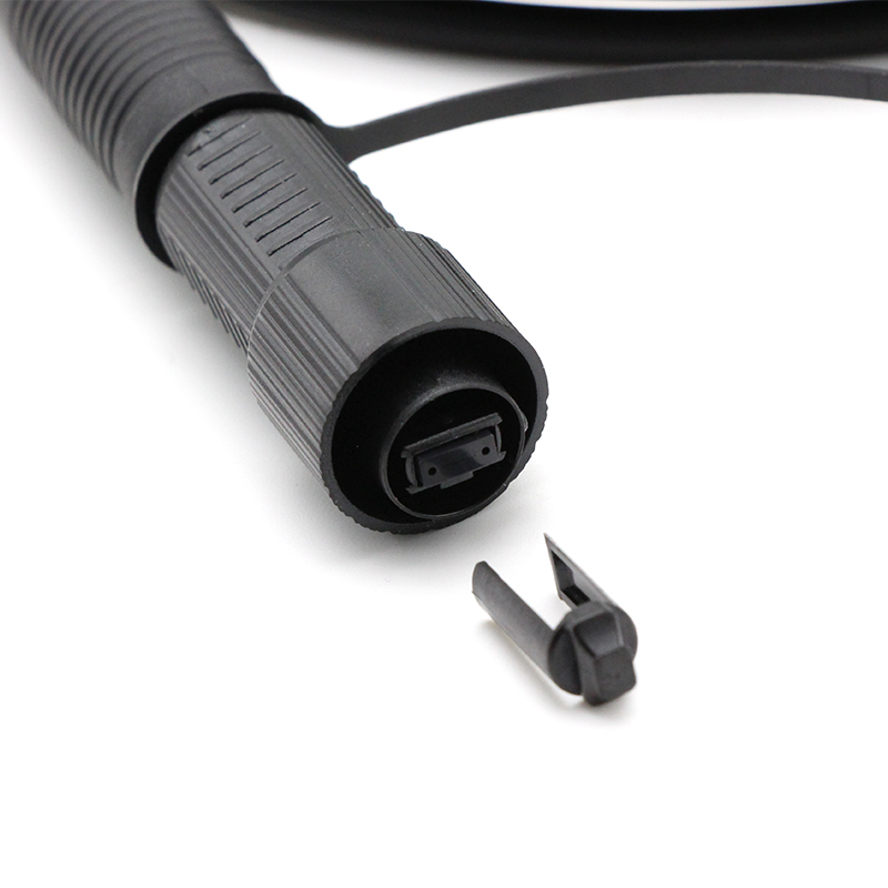
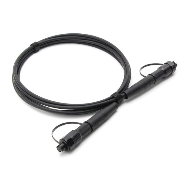
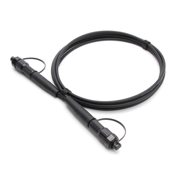
Each end of the patch cord is terminated with an Quickconnect (MPO) plug. The plug consists of a precision-molded MT ferrule that holds the twelve fibers in a single row at a 0.25 mm fiber pitch, two precision guide pins (or guide holes for the female version) with a 4.6 mm pin pitch, a spring-loaded ferrule mechanism, a molded housing, and a strain-relief boot. The spring-loaded float of the ferrule ensures physical contact between the two end faces after mating, which is essential for stable optical performance.
| Item | Connector 1 and Connector 2 |
| Type | QuickConnect MPO / APC (female) |
| Insertion loss | Max. ≤ 0.35 dB |
| Return loss | ≥ 60 dB |
| Tensile strength between cable and connector | Load: 800 N, duration: 5 s |
| Tensile strength between connector and adapter | Load: 300 N, duration: 120 s |
| Fall | Drop height: 1.5 m, number of drops: 10 |
| Static side load | Load: 50 N, duration: 1 h |
| Waterproof | IP68 |
3.2 Cable Construction
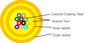
The patch cord uses a 5.0 mm double Sheath round cable. Twelve 250 µm coated single-mode fibers are positioned in the center, surrounded by aramid yarn strength members and protected by an LSZH outer jacket. The aramid yarn provides tensile strength and crush resistance, while the LSZH jacket offers flame retardance, low smoke and low toxicity emission in indoor environments.
| Parameter | Specification |
| Fiber count | 12 |
| Fiber type | OS2 single-mode (ITU-T G.652.D; G.657.A1 optional) |
| Colored Coating Fiber | Blue,Orange,Green,Brown,Grey,White,Red,Black,Yellow,Purple,Pink,Aqua |
| Fiber attenuation | ≤ 0.40 dB/km @ 1310 nm; ≤ 0.30 dB/km @ 1550 nm |
| Outer Jacket | 5.0 ± 0.2 mm LSZH Black |
| Inner Jacket | 3.0 ± 0.1 mm LSZH Black |
| Strength member | Aramid yarn |
| Parameter | Specification |
| Tensile strength — short term | ≥ 300 N |
| Tensile strength — long term | ≥ 160 N |
| Operating temperature | -20 °C ~ +60 °C |
| Storage temperature | -40 °C ~ +85 °C |
| Flame retardance | IEC 60332-1 compliant |
| Regulatory compliance | RoHS, REACH |
4. Application Scenarios
4.1 Data Center and AI / HPC Networks
The 12-fiber SM patch cord is the standard building block for parallel single-mode optics in modern data centers: 100G PSM4, 400G DR4 and 800G DR8 links using QSFP28, QSFP-DD or OSFP transceivers with MPO interfaces. It is used for switch-to-switch, switch-to-server and compute-fabric patching in spine-leaf and AI/HPC clusters where high density and low latency matter.
4.2 High-Density Patching and Cabling
With twelve fibers in a single connector, the patch cord dramatically reduces port footprint and cable count in ODFs, fiber distribution frames, patch panels and pre-terminated trunk systems, simplifying cable management, airflow and moves-adds-changes (MAC) operations in constrained rack space.
4.3 Campus, Metro and Telecom Networks
Single-mode transmission supports long-reach links across campus backbones, metro rings and central-office patching at 10G/25G/100G and beyond, providing the reach and scalability that multimode solutions cannot achieve.
4.4 Outdoor and Industrial Applications
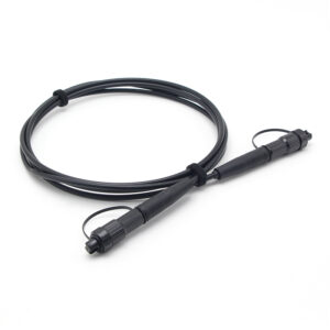
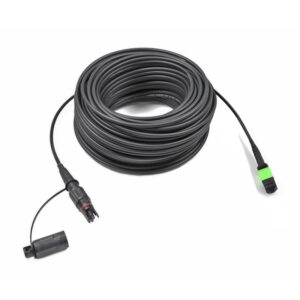
Where the ODVA connector system is specified, the ruggedized ODVA housing protects the MPO interface for outdoor, FTTA/5G fronthaul, industrial Ethernet and other harsh-environment deployments requiring reliable, weather-protected multi-fiber interconnection.
5. Standards and Compliance
The product is designed and manufactured in accordance with the following standards:
- IEC 61754-7-1:2014 — Fibre optic connector interfaces, Part 7-1: Type MPO connector family (one fibre row);
- ANSI/TIA-604-5 (FOCIS 5) — Fiber Optic Connector Intermateability Standard, Type MPO;
- IEC 60793-2-50:2025 — Optical fibres, Part 2-50: Sectional specification for class B single-mode fibres;
- ITU-T G.652 (08/2024) — Characteristics of a single-mode optical fibre and cable;
- IEC 60332-1-2:2004+A1:2015 — Tests on electric and optical fibre cables under fire conditions;
- Telcordia GR-326-CORE / GR-1435-CORE — Reliability requirements for single-mode and multi-fiber optical connectors (reference);
- RoHS (Directive 2011/65/EU) and REACH compliant.
6. Polarity
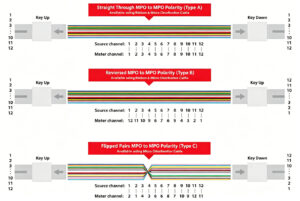
7. Length Tolerance

| Overall Length(L)(m) | length of tolerance(cm) |
| 0<L<1 | +5/-0 |
| 1<L<10 | +10/-0 |
| 10<L<40 | +15/-0 |
| 40<L | +0.5% x L/-0 |
12Cores-SM-trunk-cable-300x300.jpg "Odva(mpo) Odva(mpo)12cores Sm Trunk Cable")