
1. Introduction
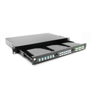
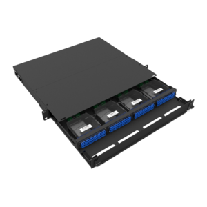
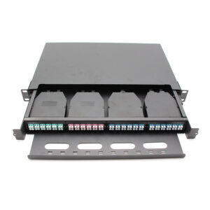
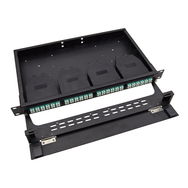
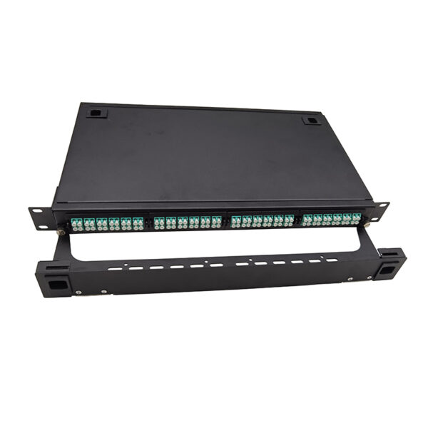
The 1U MPO-LC Chassis is a high-density, 19-inch rack-mount fiber distribution chassis designed for data center, enterprise and telecommunication applications. It occupies one rack unit (1U) of a standard 19-inch rack and provides four (4) MPO-LC module slots, each accepting one standard MPO-LC plastic cassette module or adapter panel. With four 24F cassettes installed, the chassis manages up to 96 fibers and 96 LC ports in a single rack unit.
The chassis converts high-density MPO/MTP trunk connections on the rear into individual LC duplex patch connections on the front. It enables efficient break-out, patching and management of high-fiber-count backbone links, such as those used in 40G/100G/200G/400G networks, while keeping a small footprint and easy front access for moves, adds and changes (MACs).
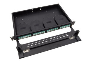
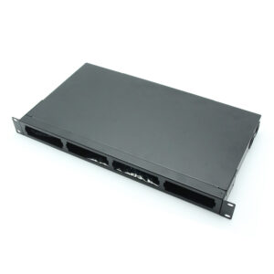
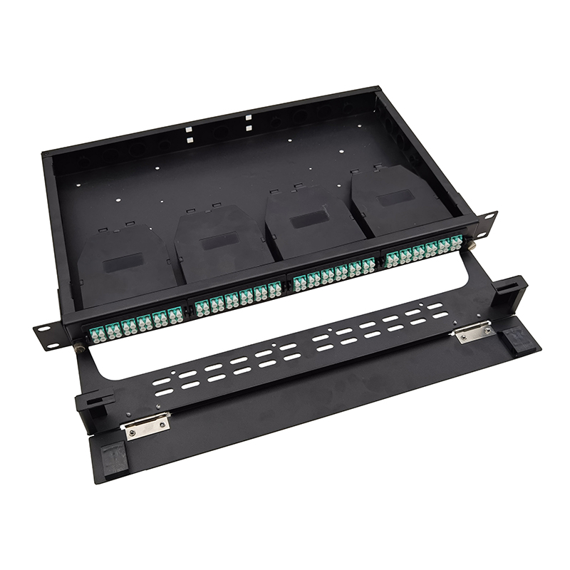
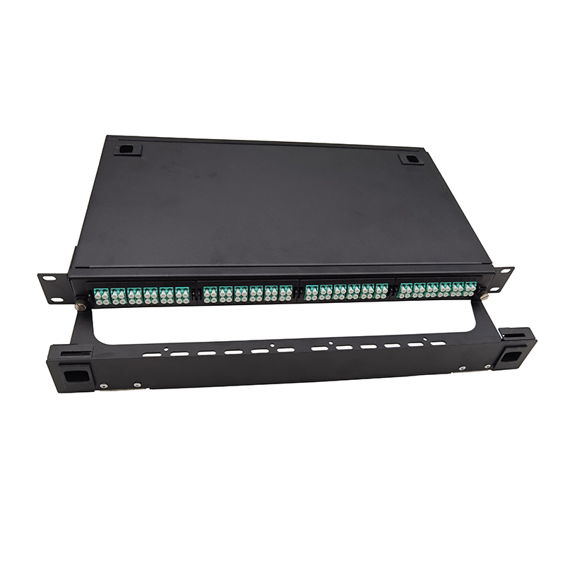
Figure 1. 1U 19-inch rack-mount MPO-LC chassis (representative product) with front cable management
2. Key Features
- High fiber density: up to 96 LC ports (48 LC duplex) in a single 1U rack unit when fitted with four 24F MPO-LC cassettes.
- Module standard compatibility accepts standard-size MPO-LC cassette modules (LGX / FHD form factor) from mainstream suppliers.
- MPO/MTP to LC break-out: rear MPO-12 or MPO-24 trunk input, front LC duplex output, UPC or APC polish.
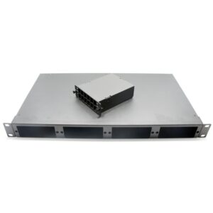
- Tool-less module installation: cassettes snap into the slots and are secured with a release latch – no tools required.
- Front-access patching: all LC ports are located on the front for quick and convenient patching.
- Robust construction: cold-rolled steel body with black powder-coated finish; rack-mounting ears supplied.
- Flexible configurations: supports 12F and 24F MPO cassettes in OM3, OM4, OM5 multimode or OS2 single-mode fiber.
- Integrated cable management: guided trunk and patch routing with adequate bend-radius control.
- Flexible configurations: supports 12F and 24F MPO cassettes in OM3, OM4, OM5 multimode or OS2 single-mode fiber.
- Integrated cable management: guided trunk and patch routing with adequate bend-radius control.
3. Technical Specifications
The tables below list the nominal specifications of the chassis. Values marked with an asterisk (*) are standard rack-unit or industry-typical values; final specifications are subject to the ordered model.
Table 1. Mechanical specifications
| Item | Specification |
| Chassis width | 482.6 mm (19″) including mounting ears * |
| Chassis height | 44.0 mm (1U) * |
| Chassis depth | 343mm |
| Module slots | 4 |
| Housing material | Cold-rolled steel (SPCC) or Aluminum alloy , powder coated |
| Color | Black (RAL 9005) * |
| Weight | Approx. 2.0 kg (empty, typical) |
Table 2. Capacity
| Item | Specification |
| Module slots | 4 |
| Max. LC ports (24F MPO cassettes) | 96F LC ports (48 LC duplex) |
| Max. LC ports (12F MPO cassettes) | 48 LC ports (24 LC duplex) |
| MPO trunk ports (rear) | 1 x MPO-12 or MPO-24 per module |
| Total fiber capacity | Up to 96 fibers (4 x 24F) |
Table 3. Environmental and compliance
| Item | Specification |
| Operating temperature | -10 °C to +60 °C (typical) * |
| Storage temperature | -40 °C to +70 °C (typical) * |
| Relative humidity | 5% – 95%, non-condensing (typical) * |
| Compliance | RoHS; CE / FCC options available on request |
4. Product Structure
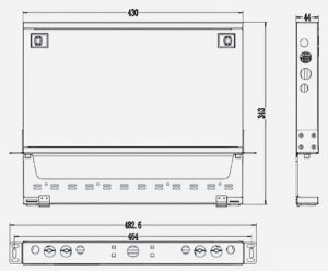
Figure 2. Cable Drawing (schematic, not to scale)
| No. | Component | Description |
| 1 | Rack mounting ear | 19-inch rack-mount brackets with fixing holes (M5/10-32) |
| 2 | MPO-LC module slot (x4) | 4 Slots openings accepting cassettes or adapter panels |
| 3 | LC duplex adapter | Front LC duplex ports of the installed cassette (8F,12F,24F Per module) |
| 4 | Module release latch | Tool-less latch that secures and releases the cassette |
| 5 | MPO trunk port (rear) | Rear MPO-8/MPO-12 / MPO-24 trunk connection of the cassette |
5. Compatible Modules
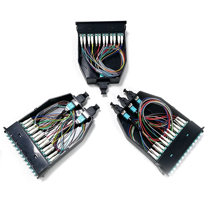
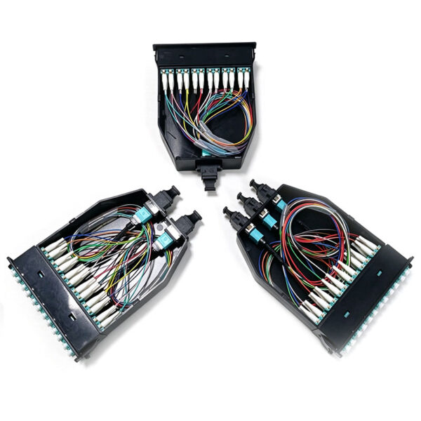
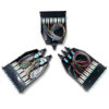
The chassis accepts MPO-LC cassette modules with typical dimensions of approximately 101 mm (W) x 33 mm (H) x 152 mm (D). MPO-LC cassettes provide a plug-and-play break-out between a rear MPO/MTP trunk connector and front LC duplex ports, eliminating field splicing for high-speed network links.
Table 5. Module configuration options
| 1 x 24F MPO to 12x LC duplex | Front ports | Rear port | Material | Dimension(mm) |
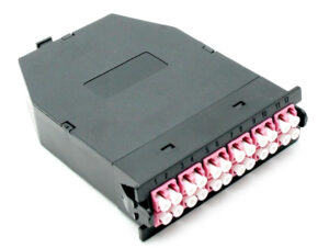 |
12x LC duplex (24 LC) | 1 x MPO-24 | ABS | 152*101*33 |
| 1 x 16F MPO to 8x LC duplex | Front ports | Rear port | Material | Dimension(mm) |
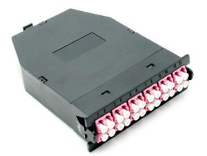 |
8x LC duplex (16 LC) | 1 x MPO-16 | ABS | 152*101*33 |
| 2 x 12F MPO to 12x LC duplex | Front ports | Rear port | Material | Dimension(mm) |
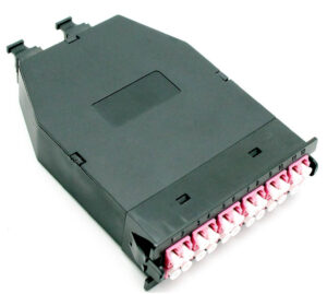 |
12x LC duplex (24 LC) | 2 x MPO-12 | ABS | 152*101*33 |
| 3 x 8F MPO to 12x LC duplex | Front ports | Rear port | Material | Dimension(mm) |
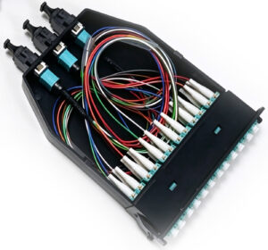 |
12x LC duplex (24 LC) | 3 x MPO-8 | ABS | 152*101*33 |
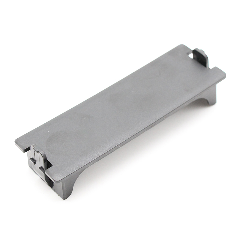
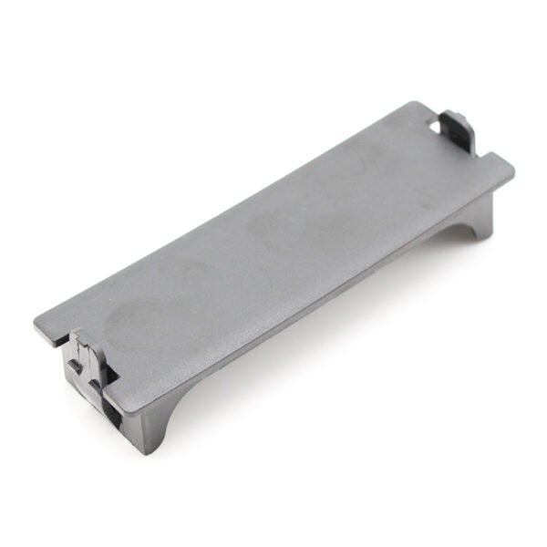
| Blank plate | Front ports | Rear port | Material | Dimension(mm) |
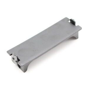 |
/ | / | ABS | 101*33 |
Available options: fiber type OM3 / OM4 / OM5 / OS2; polish UPC or APC; polarity mapping Type A / B / C. Contact the sales team for customized configurations.
6. Other Accessories
| 8F MPO-LC 0.9mm fanout 30cm | End A | End B | Optical Performance |
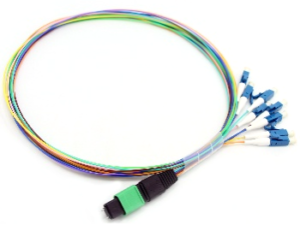 |
1x8F MPO&MTP(Male) with Pin | 8x LC simplex 0.9 connectors | Standard MPO IL<0.5dB
Super low loss MPO IL<0.35dB LC ‘s IL<0.3dB
|
| 12F MPO-LC 0.9mm fanout 30cm | End A | End B | Optical Performance |
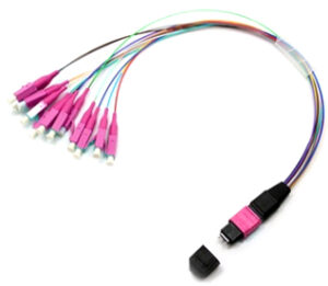 |
1x12F MPO&MTP(Male) with Pin | 12x LC simplex 0.9 connectors | Standard MPO IL<0.5dB
Super low loss MPO IL<0.35dB LC ‘s IL<0.3dB
|
| 24F MPO-LC 0.9mm fanout 30cm | End A | End B | Optical Performance |
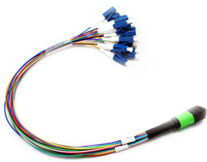 |
1x24F MPO&MTP(Male) with Pin | 24x LC simplex 0.9 connectors | Standard MPO IL<0.5dB
Super low loss MPO IL<0.35dB LC ‘s IL<0.3dB
|
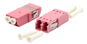
| LC DX Reduced flange Adapter | Keyway | Footprint | Insertion Loss | Color |
 |
Aligned (Up-Up)
|
SC Footprint | ≤0.2dB | SM:BLUE
OM3:AQUA OM4:MAGENTA OM5:LIME GREEN |
| MPO Adapter | Keyway | Footprint | Insertion Loss | Color |
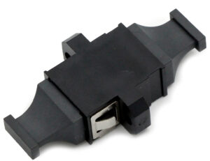 |
Opposed (Up-Down) Aligned (Up-Up) |
MPO/MTP standard | ≤0.2dB | Black |
7. Application Scenarios
The chassis is designed for high-density patching and break-out in fiber-optic networks. Typical application scenarios include:
- Data center structured cabling (EoR / MoR): high-density patching between spine and leaf switches and servers.
- High-speed network break-out: QSFP-DD / QSFP28 400G or 100G MPO trunk links break out to 100G / 25G / 10G LC ports.
- Enterprise LAN / WAN and campus backbone consolidation.
- Storage area networks (SAN) and high-performance computing (HPC) clusters.
- Telecommunication central offices, FTTx and access networks.
- Meet-me rooms and co-location cross-connect areas requiring dense, organized fiber patching.
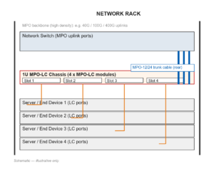
Figure 4. Typical data center application (schematic)
8. Installation
8.1 Unpacking and inspection
Before installation, check the package contents and inspect the product for any damage caused during transport. Standard package contents: 1U chassis x 1, rack-mounting screw kit, cable ties, and this manual.
8.2 Rack mounting
- Select an available 1U space in a standard 19-inch rack.
- Hold the chassis horizontally and slide it into the rack opening from the front.
- Align the fixing holes of the mounting ears with the rack rail holes.
- Secure the chassis with four screws (M5 or 10-32, supplied) – two on each side.
- Verify that the chassis is level and firmly fastened before loading modules or cables.
8.3 Module installation
MPO-LC cassette modules are installed without tools, as shown in Figure 5.
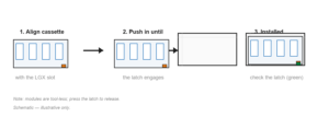
Figure 5. Module installation steps (schematic)
- Align the cassette with a module slot on the front of the chassis.
- Push the cassette straight into the slot until the release latch clicks and locks.
- Check that the cassette is fully seated and the latch is engaged.
- To remove a module, press the release latch and pull the cassette straight out.
8.4 Cable routing
Connect the MPO/MTP trunk cable to the rear MPO port of each cassette, and patch the front LC duplex ports to the end devices. Keep the cable bend radius above the minimum value recommended for the cable type (typically at least 10 times the cable outer diameter), secure cables with the supplied cable ties, and leave sufficient slack for future moves and adds.
8.5 Polarity check
Before commissioning, verify that the polarity mapping (Type A / B / C) of the installed cassettes matches the network design, and confirm the fiber type and polish of the trunk and patch cords are consistent end to end.
9. Maintenance and Safety
- Keep dust caps on all unused ports to protect the connector end faces.
- Clean connector end faces with approved ferrule cleaning tools or lint-free wipes and isopropyl alcohol before every connection.
- Do not exceed the minimum bend radius of the cables; avoid sharp bends, crushing or tension.
- Laser safety: never look directly into optical ports. Optical transceivers may emit invisible laser radiation (Class 1M); cover unused ports when the system is energized.
- Store the product in a dry, dust-free environment within the specified temperature and humidity ranges.
- Inspect the installation periodically: verify connector cleanliness, latch engagement and cable routing.
10. Ordering Information
Contact the sales team to confirm part numbers and configurations. Custom module types, fiber grades and connector polishes are available on request.
Table 6. Ordering information (Unloaded patch panel)
| Item | Part No. | Description | |
| 1U MPO-LC Fixed chassis 96F | FHD4F1-4 |
|
|
| 1U MPO-LC Fixed chassis 96F | FHD4F2-4 | 1U FHD MPO/MTP-LC 96F Fixed Rack mounted Chassis
-4 cassettes modular Design Aluminum alloy Material |
Table 7. Ordering information (Full loaded MPO/MTP-LC Cassette)
| Cassette | – | Material | – | MPO adapter | – | LC adapter | – | Adapter Port | – | MPO/MTP Quality level | – | Fiber mode |
| FHD2S0-(Blank plate) | 1-Black Color | 0-unloaded | 0-unloaded | 0-(Blank plate) | 0-Unloaded | 0– Unloaded | ||||||
| FHD2S1-Cassette | 2-Transparent | 1-Opposed (Up-Down) | 1-LC Standard Quad no flange | 1-(1xMPO-4xLC DX) | 1-Standard loss MPO Male Senko | 1– G657A1 | ||||||
| 2-Aligned (Up-Up) | 2-LC DX no flange adapter-SC footprint | 2 –
(1xMPO-6xLC DX) |
2-Super low loss MPO Male Senko | 2-G657A2/B2 | ||||||||
| 3-LC DX with flange adapter-SC footprint | 3 –
(1xMPO-12xLC DX) |
3-Standard loss MTP Male | 3-G657B3 | |||||||||
| 4- (2xMPO-12xLC DX) | 4-Super low loss Elite MTP Male | 4-BIF OM1 | ||||||||||
| 5- (3xMPO-12xLC DX) | 5-Standard loss MPO Male OMC | 5-BIF OM2 | ||||||||||
| 6-Super low loss MPO Male OMC | 6-BIF OM3 | |||||||||||
| 7-BIF OM4 | ||||||||||||
| 8-BIF OM5 |
For Example:FHD2S1-1-2-2-3-1-1