
1.Product Construction
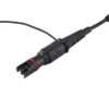
1.1 OP (MPO) Hardened Connector End
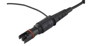
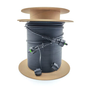
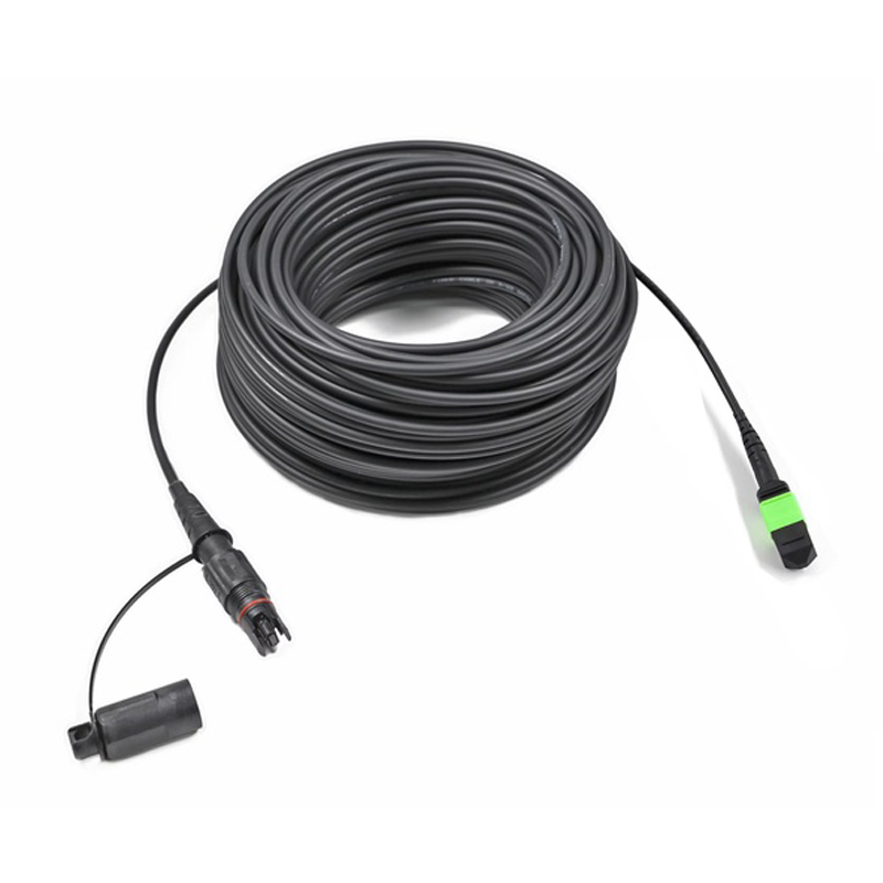
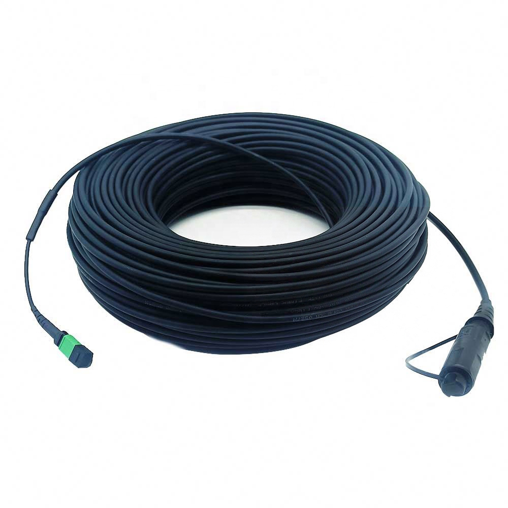
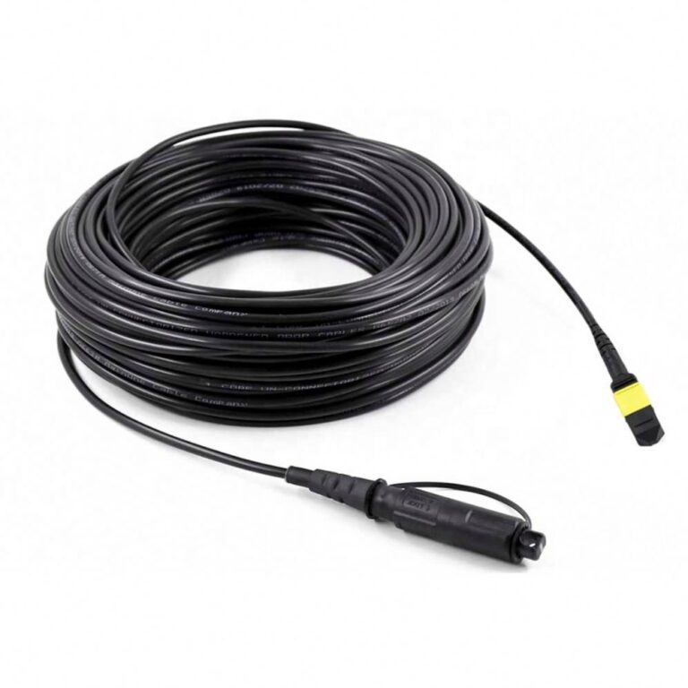
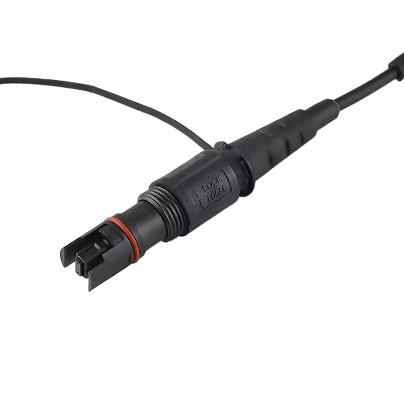
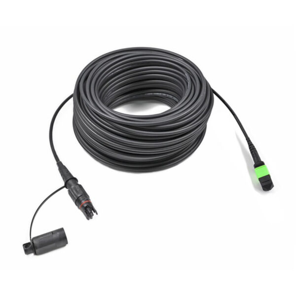
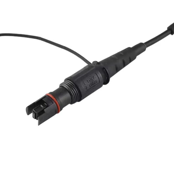
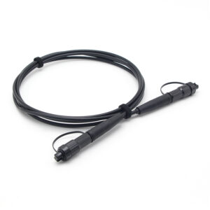
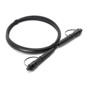
The hardened end is an OptiTap-type outdoor connector with an MPO interface inside. It consists of a precision MT ferrule holding the twelve fibers, an environmentally sealed housing with an O-ring seal, a threaded (or bayonet) coupling nut for secure engagement with the hardened adapter, and a strain-relief boot. The hardened construction protects the MPO interface from moisture, dust and mechanical impact when exposed outdoors.
Table 1 — OptiTap (MPO) hardened connector components
| Component | Material / Structure | Function |
| MT ferrule | Precision-molded polymer, 12-fiber, 0.25 mm pitch | Positions and aligns the twelve fibers |
| Housing and seal | Ruggedized polymer + O-ring seal | Environmental sealing, impact protection |
| Coupling nut | Threaded / bayonet, hand-tightenable | Secure engagement with hardened adapter |
| Strain-relief boot | Elastomer | Bend and pull protection at cable exit |
1.2 MPO Standard Connector End
Table 2 — Standard MPO
| Connector | Fiber Channel |
 |
 |
| MPO Female Connectors | 12 Fibers |
| Note: Female connector need to connect with male connector type. | |
The standard MPO end follows the MPO interface defined by IEC 61754-7-1 and ANSI/TIA-604-5 (FOCIS 5), with a spring-loaded MT ferrule, guide pins (male) or guide holes (female), a keyed housing and a push–pull latch. It mates with standard MPO adapters and MPO-based transceiver interfaces in protected indoor environments.
1.3 Cable Construction.
Table 3 — Cable cross-section layers
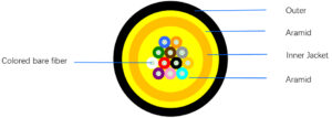
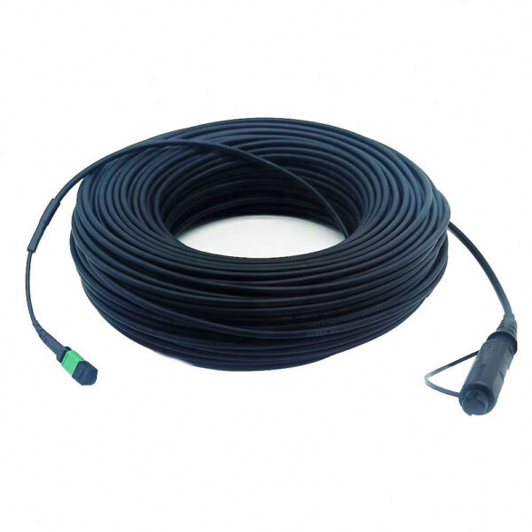
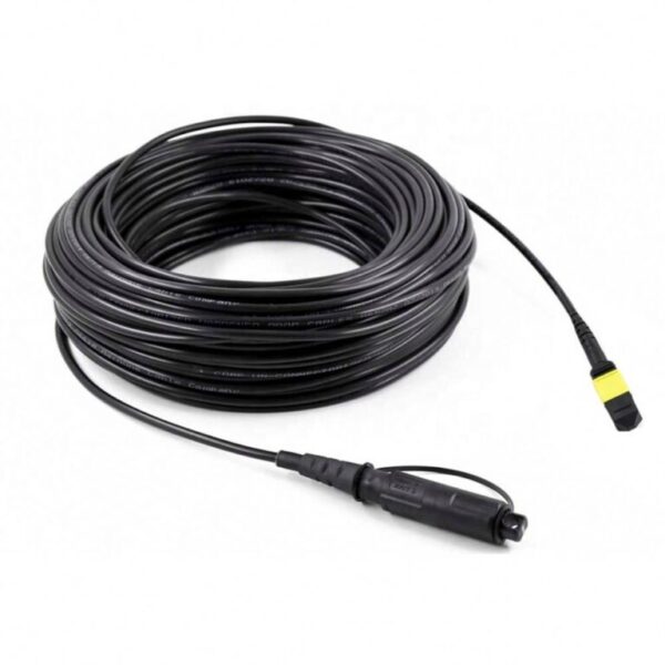
The patch cord uses a 5.0 mm round cable. Twelve 250 µm coated single-mode fibers are protected by aramid yarn strength members and an LSZH outer jacket, providing tensile strength, crush resistance and indoor fire safety.
2.Design Principle
2.1 Parallel-Optics Architecture
The MPO interface is the physical foundation of parallel optical transmission. A single 12-fiber connector carries twelve independent lanes in parallel, each transmitting one optical channel (e.g., 25 G, 50 G or 100 G per lane). This architecture directly matches the MPO-based interfaces of high-speed transceivers such as 100G PSM4, 400G DR4 and 800G DR8, and replaces multiple simplex connectors with one plug for high-density cabling.
2.2 Precision Alignment Mechanism
Fiber-to-fiber alignment is achieved by a passive precision mechanism. Guide pins of the male plug enter the precision guide holes of the female plug and center the two MT ferrules to micron-level accuracy, aligning all twelve fiber cores simultaneously. A compression spring behind the ferrule maintains physical contact between the end faces under controlled force, keeping insertion loss low and stable.
2.3 End-Face Polishing
For single-mode transmission, the ferrule end faces are polished at an 8° angle (APC). The angled end face directs Fresnel back reflections away from the optical path, achieving a return loss of 60 dB or higher. Combined with physical contact under spring load, the design ensures stable optical performance across repeated mating cycles.
2.4 Hardened Sealing and Coupling
The OptiTap (MPO) end is designed for outside-plant exposure: the O-ring-sealed housing and the locking coupling nut provide IP68 protection against rain, humidity and immersion, while the robust housing and strain relief tolerate field handling, pole and facade mounting. This makes the hardened end the weather-proof anchor of the link, with the standard MPO end kept in protected indoor spaces.
3.Technical Specifications
Table 4 — Connector specifications
| Parameter | Specification |
| Connector 1 (outdoor end) | OptiTap (MPO), hardened, IP68 rated |
| Connector 2 (indoor end) | MPO, standard, push–pull |
| Ferrule | MT, precision-molded, single row of 12 fibers |
| Fiber pitch | 0.25 mm |
| Guide pin pitch / pin diameter | 4.6 mm / Ø0.7 mm |
| Gender | Male (with pins) / Female (without pins), per end |
| Keying | Key-up / Key-down |
| End-face polish | APC 8° (standard); UPC optional |
| Mating durability | ≥ 500 cycles |
Table 5— Optical performance (per mated pair, after cleaning)
| Parameter | Typical | Maximum |
| Insertion loss @ 1310 / 1550 nm | ≤ 0.30 dB | ≤ 0.50 dB |
| Return loss (APC) | ≥ 60 dB | — |
| Test wavelength | 1310 nm / 1550 nm | — |
Table 6 — Mechanical and environmental specifications
| Parameter | Specification |
| Tensile strength — short term | ≥ 300 N |
| Tensile strength — long term | ≥ 160 N |
| Waterproof (hardened end) | IP68 |
| Operating temperature | -40 °C ~ +70 °C |
| Storage temperature | -40 °C ~ +85 °C |
| Flame retardance | IEC 60332-1 compliant |
| Regulatory compliance | RoHS |
4.Standards and Compliance
The product is designed and manufactured in accordance with the following standards:
- IEC 61754-7-1:2014 — Fibre optic connector interfaces, Part 7-1: Type MPO connector family (one fibre row);
- ANSI/TIA-604-5 (FOCIS 5) — Fiber Optic Connector Intermateability Standard, Type MPO;
- IEC 60793-2-50:2025 — Optical fibres, Part 2-50: Sectional specification for class B single-mode fibres;
- ITU-T G.652 (08/2024) / G.657 (08/2024) — Characteristics of single-mode and bending-loss insensitive single-mode optical fibres;
- IEC 60529 — Degrees of protection provided by enclosures (IP Code); the waterproof rating IP68 is defined in accordance with this standard;
- IEC 60332-1-2:2004+A1:2015 — Tests on electric and optical fibre cables under fire conditions;
- RoHS (Directive 2011/65/EU) and REACH compliant.
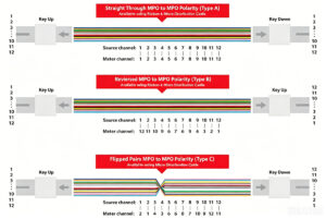
5.Polarity
6.Length Tolerance
| Overall Length(L)(m) | length of tolerance(cm) |
| 0<L<1 | +5/-0 |
| 1<L<10 | +10/-0 |
| 10<L<40 | +15/-0 |
| 40<L | +0.5% x L/-0 |
12Cores-SM-trunk-cable-300x300.jpg "Odva(mpo) Odva(mpo)12cores Sm Trunk Cable")