
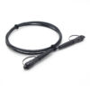
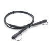
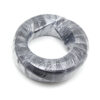
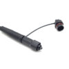
1. Features and Benefits
- Fast deployment, plug and play: the preconnectorized design eliminates field splicing and simplifies installation procedures;
- Low-insertion-loss MPO technology for stable optical performance;
- All-dielectric non-metallic round cable: light weight and excellent pull-resistant performance;
- High long-term reliability in extreme environments, with resistance to UV aging and acid-base salt corrosion;
- Waterproof rating meets IP68 requirements;
- The connector is fixed by rotation and locking, making installation and removal easy;
- Anti-pull force up to 800 N, effectively ensuring the quality of optical cable construction.
2. General Specifications
Table 1 — General specifications
| Item | Specification |
| Cable assembly type | Feeder assembly |
| Environment | Outdoor |
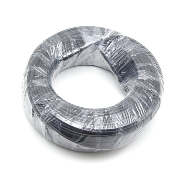
| Packaging | Individual pack |
| Application | Aerial |
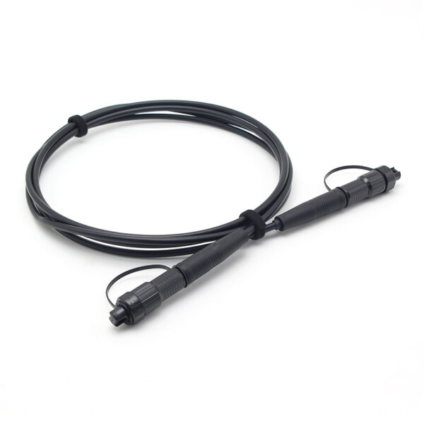
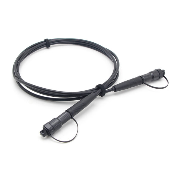
| Termination | Dual-end QuickConnect MPO (female) connectors |
| Working temperature range | -40 °C to +70 °C |
| Working humidity | 0% to 95% RH |
| Min. installation temperature | -10 °C |
| Transport temperature range | -40 °C to +70 °C |
3. Product Construction
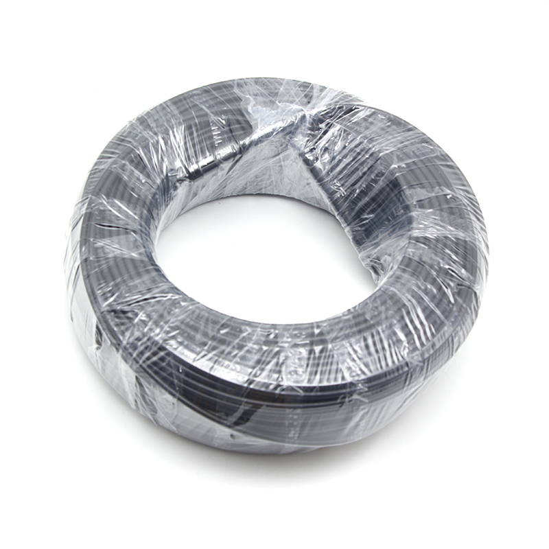
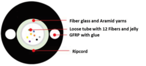
The feeder cable adopts the GYFXTY 12B6a1 construction: a gel-filled loose-tube cable core with twelve color-coded G.657A1 fibers, non-metallic strength members and a water-blocked, HDPE-jacketed round profile. The structure is fully non-metallic (all-dielectric), which eliminates the need for grounding and bonding, and improves lightning and corrosion resistance in outdoor installation.
Table 2 — Dimensions and descriptions of cable construction
| Component | Material / Structure | Function |
| Optical fibers | 12 × G.657A1 single-mode, 12 standard colors | Bend-insensitive signal transmission |
| Loose tube | PBT, outer diameter 2.1 mm | Protects the fibers; gel-filled for water blocking |
| Water blocking material | Tube jelly (in loose tube); fiber glass yarn (between loose tube and outer sheath) | Longitudinal water blocking |
| Strength member | GFRP (glass-fiber reinforced plastic) | Non-metallic tensile strength |
| Ripcord | 1 piece | Easy sheath stripping during installation |
| Outer sheath | PE (black), cable diameter 5.8 mm | Mechanical protection, weather resistance |
| Finished cable reference weight | Approx. 30 kg/km | Light weight for easy handling |
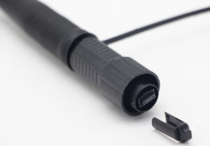
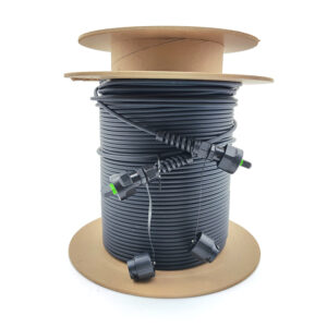
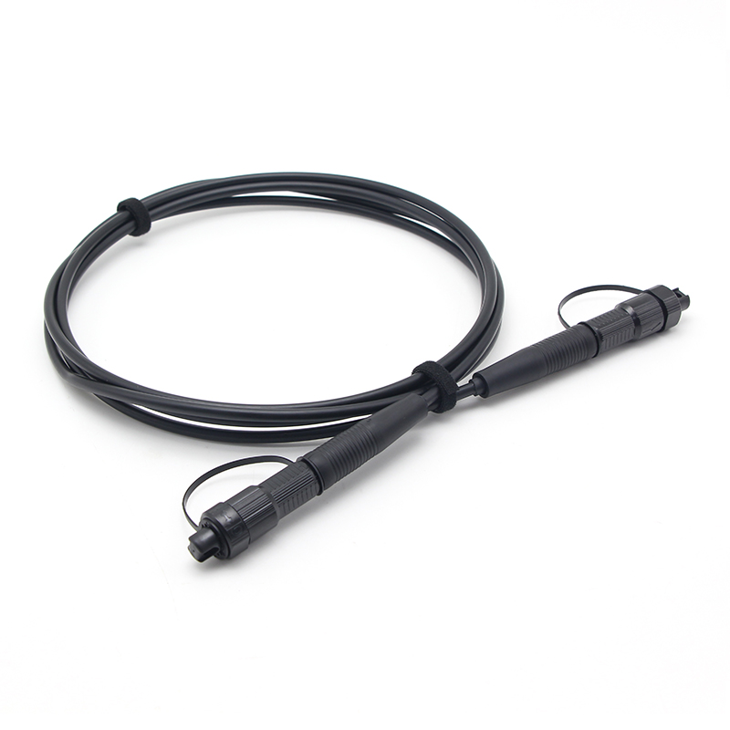
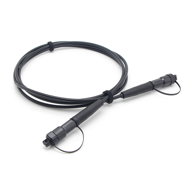
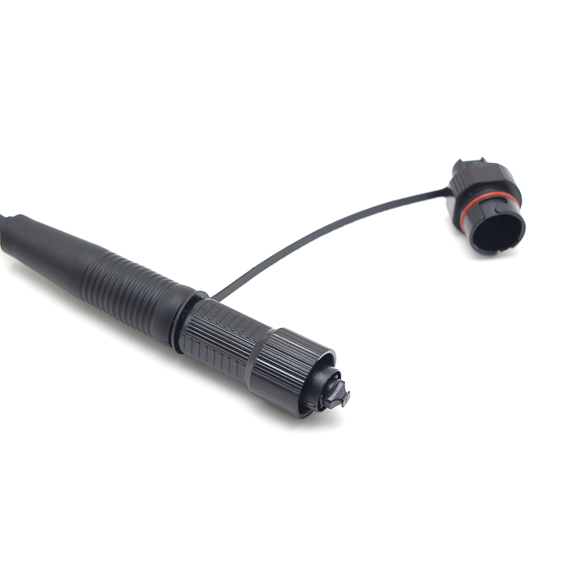
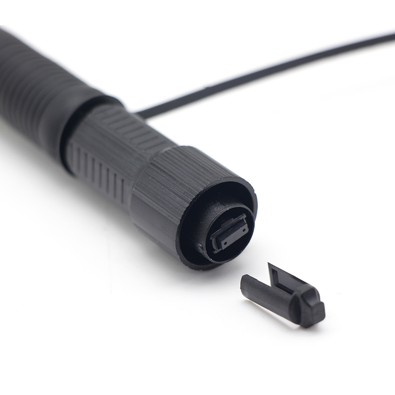
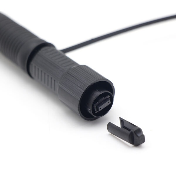
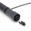
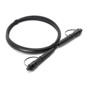
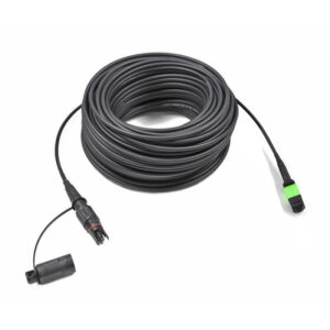
Each end of the patch cord is terminated with a Mini IP(MPO) be compatible with Quickconnect (MPO) plug. The plug consists of a precision-molded MT ferrule that holds the twelve fibers in a single row at a 0.25 mm fiber pitch, two precision guide pins (or guide holes for the female version) with a 4.6 mm pin pitch, a spring-loaded ferrule mechanism, a molded housing, and a strain-relief boot. The spring-loaded float of the ferrule ensures physical contact between the two end faces after mating, which is essential for stable optical performance.
4. Design and Engineering Principle
4.1 Preconnectorized Plug-and-Play Architecture
Both cable ends are factory-terminated with hardened QuickConnect MPO connectors. This preconnectorized architecture moves termination quality control from the construction site to the factory, enabling direct plug-and-play connection to OLT ports, ODF adapters, splitter modules or distribution boxes without fusion splicing.
4.2 All-Dielectric Cable Design
The cable uses a GFRP strength member and fiber glass yarns instead of metallic elements. The all-dielectric design avoids grounding and bonding requirements, and provides inherent immunity to lightning strikes and corrosion, which is essential for long aerial service in outdoor environments.
4.3 Water-Blocking Design
Tube jelly inside the loose tube and water-blocking fiber glass yarn between the loose tube and the outer sheath prevent longitudinal water penetration along the cable core. Combined with the IP68-rated hardened connectors, the assembly maintains optical performance under rain, humidity and immersion conditions typical of outdoor deployment.
4.4 Bend-Insensitive Fiber Selection
ITU-T G.657A1 fiber provides improved macrobending performance compared with standard G.652 fiber, giving extra layout margin at poles, building entries and cable bends, and contributing to stable low attenuation over the service life.
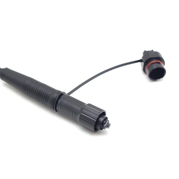
4.5 Hardened Connector and Rotation Locking
The QuickConnect connector is fixed by rotation and locking, which ensures a reliable mechanical and optical interface while allowing quick installation and removal by hand. The 800 N anti-pull capability between cable and connector protects the termination during construction pulling and long-term wind/ice loading.
5. Application in Telecom Construction Layout
5.1 Role in the Optical Distribution Network (ODN)
In fiber access network construction, the optical distribution network (ODN) is divided into feeder, distribution and drop segments. This preconnectorized feeder cable is typically deployed in the feeder section between the OLT (central office) and the optical splitter / distribution point. Because both ends are factory-terminated with hardened MPO connectors, the cable can be plugged directly into the OLT port, ODF adapter, splitter module or outdoor distribution box, eliminating on-site fusion splicing together with its equipment, skilled labor and quality risks.
5.2 Aerial Deployment and Span Layout
Aerial installation is the primary deployment method for this product. During construction layout planning, the pole spacing (span), the installation sag ratio and the expected weather loads (wind speed and ice thickness) must be coordinated with the mechanical limits of the cable. The table below provides reference span and sag values calculated for this cable under typical weather conditions.
Table 3 — Aerial deployment layout reference (span / sag / tensile under weather conditions)
| Weather condition | Max. span (m) | Installation sag ratio | Installation sag (m) | Installation tensile (N) | Weather load tensile (N) | Weather load sag (m) | Weather load sag ratio |
| Max. wind speed: 37 m/s, ice: 0 | 30 | 0.60% | 0.18 | 183 | 600 | 0.63 | 2.13% |
| Max. wind speed: 26.67 m/s, ice: 0 | 50 | 1.00% | 0.5 | 183 | 597 | 1.13 | 2.26% |
| Max. wind speed: 10.7 m/s, ice: 6.35 mm | 50 | 1.00% | 0.5 | 183 | 659 | 1.23 | 2.45% |
| Max. wind speed: 26.67 m/s, ice: 0 | 80 | 1.50% | 1.2 | 195 | 768 | 2.25 | 2.82% |
Note: The aerial span depends on the installation and weather conditions. This table is for calculation reference. If the installation conditions exceed this table, please request technical support.
5.3 Installation Guidelines for Construction Sites
- Pulling: keep the installation tensile within the rated limits (1350 N short-term for the cable; 800 N anti-pull at the connector); do not exceed the 800 N long-term rating during service;
- Bending: maintain the minimum bend radius of 60 mm (static) and 120 mm (dynamic) during layout,fixing and storage;
- Temperature: do not install when the ambient temperature is below -10 °C;
- Connector mating: insert the connector and rotate to lock; verify correct engagement to prevent loosening under wind load;
- Sheath handling: use the built-in ripcord to strip the sheath and keep the water-blocking layers intact at terminations.
5.4 Benefits in Telecom Construction
- Splice-free plug-and-play: shortens construction time and reduces on-site labor and tooling;
- Consistent optical performance: factory-terminated connectors ensure an insertion loss of ≤ 0.35 dB per connector;
- Weather-proof terminations (IP68): permits direct outdoor exposure at poles, distribution boxes and building entries;
- Light all-dielectric cable (approx. 30 kg/km): easier hauling and reduced support requirements on poles;
- Fewer failure points: no field splicing points in the feeder section lowers the risk of link degradation.
6. Technical Specifications
Table 4 — Cable mechanical and environmental performance
| Parameter | Specification |
| Tensile performance (short term / long term) | 1350 / 800 N |
| Cable crush (short term / long term) | 2200 / 1100 N/100 mm |
| Min. bend radius (static / dynamic) | 60 / 120 mm |
Table 5 — Connector optical and mechanical specifications
| Item | Connector 1 and Connector 2 |
| Type | QuickConnect MPO / APC (female) |
| Insertion loss | Max. ≤ 0.35 dB |
| Return loss | ≥ 60 dB |
| Tensile strength between cable and connector | Load: 800 N, duration: 5 s |
| Tensile strength between connector and adapter | Load: 300 N, duration: 120 s |
| Fall | Drop height: 1.5 m, number of drops: 10 |
| Static side load | Load: 50 N, duration: 1 h |
| Waterproof | IP68 |
Note: The IL values above refer to the connector insertion loss only. The total product insertion loss must include both the connector IL and the cable IL: IL_total = 2 × IL(connector) + IL(1 km cable) / 1000 × L (cable length in m).
Table 6 — Fiber specifications
| Parameter | Specification |
| Fiber mode | Single mode |
| Fiber type | ITU-T G.657A1 |
| Maximum attenuation | 1310 nm: 0.36 dB/km; 1550 nm: 0.22 dB/km |
7. Standards and Compliance
The product is designed, manufactured and tested in accordance with the following standards:
- IEC 61753-1:2018 — Fibre optic interconnecting devices and passive components, Performance standard, Part 1: General and guidance (test standard);
- ITU-T G.657 (08/2024) — Characteristics of a bending-loss insensitive single-mode optical fibre and cable (fiber type);
- IEC 60529 — Degrees of protection provided by enclosures (IP Code); the waterproof rating IP68 is defined in accordance with this standard;
- RoHS 2.0 (Directive 2011/65/EU) — compliant.
8. Polarity
9. Length Tolerance

| Overall Length(L)(m) | length of tolerance(cm) |
| 0<L<1 | +5/-0 |
| 1<L<10 | +10/-0 |
| 10<L<40 | +15/-0 |
| 40<L | +0.5% x L/-0 |
P.S: 24F is available too
12Cores-SM-trunk-cable-300x300.jpg "Odva(mpo) Odva(mpo)12cores Sm Trunk Cable")