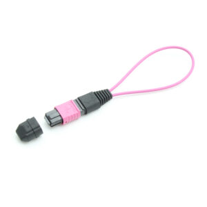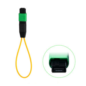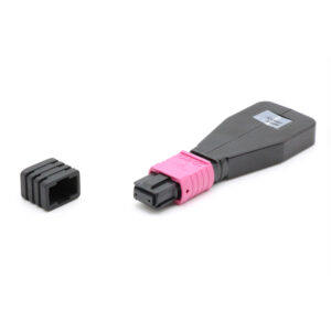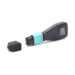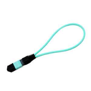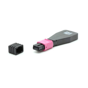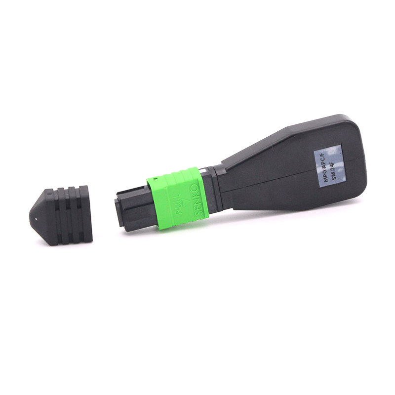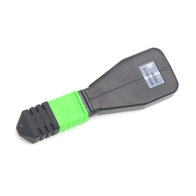

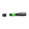
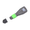
2. Key Features
- 24-fiber MPO connector supporting 100G/400G/800G parallel optics architectures
- Push-pull coupling mechanism for tool-free insertion and extraction
- Available in Singlemode (OS2, 9/125 um) and Multimode (OM3/OM4/OM5, 50/125 um)
- UPC and APC polish options for singlemode; UPC for multimode
- Low insertion loss and high return loss for reliable test accuracy
- Configurable polarity: Type A, Type B, Type C, or custom mapping
- Compact form factor suitable for high-density panel environments
- LSZH (Low Smoke Zero Halogen) housing for enhanced safety
- Compatible with standard MPO-24 adapters, cassettes, and transceiver interfaces
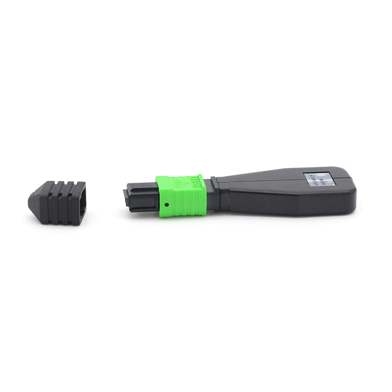
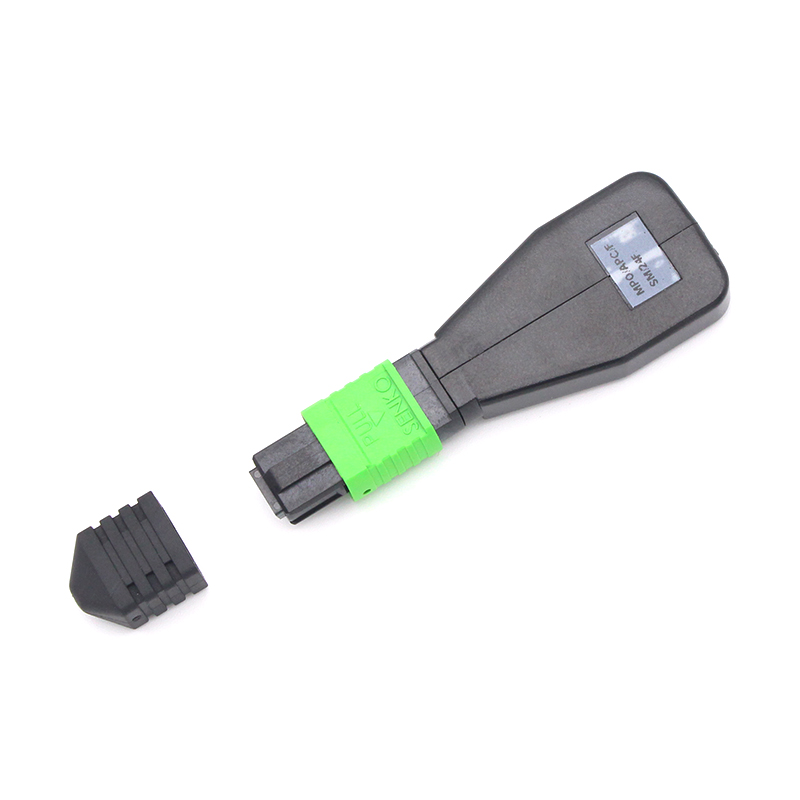
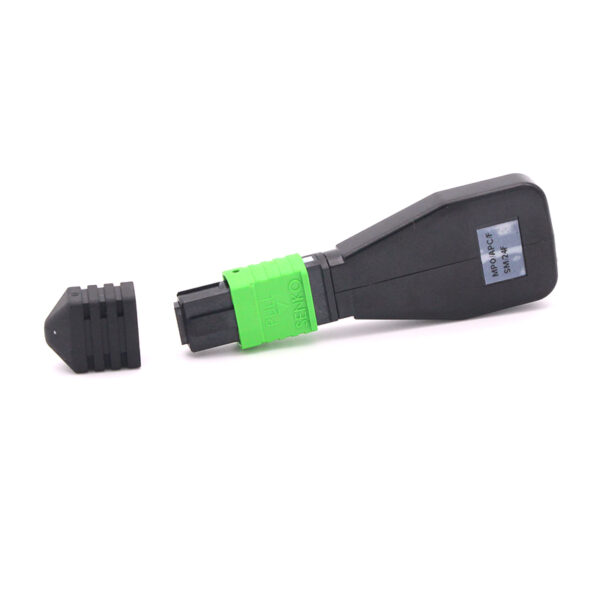
- Protective dust cap included for end-face contamination prevention
- Supports 2×12 fiber split configurations for dual MPO-12 transceiver testing
- Ideal for testing QSFP28, QSFP-DD, and OSFP transceiver form factors
3. Technical Specifications
3.1 General Parameters
| Parameter | Specification |
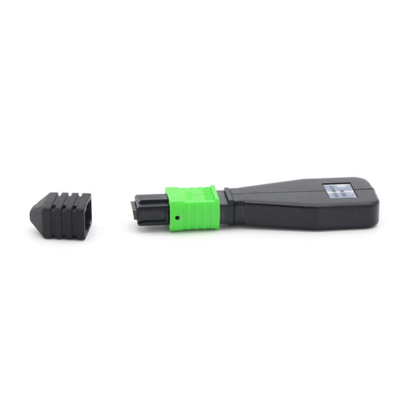
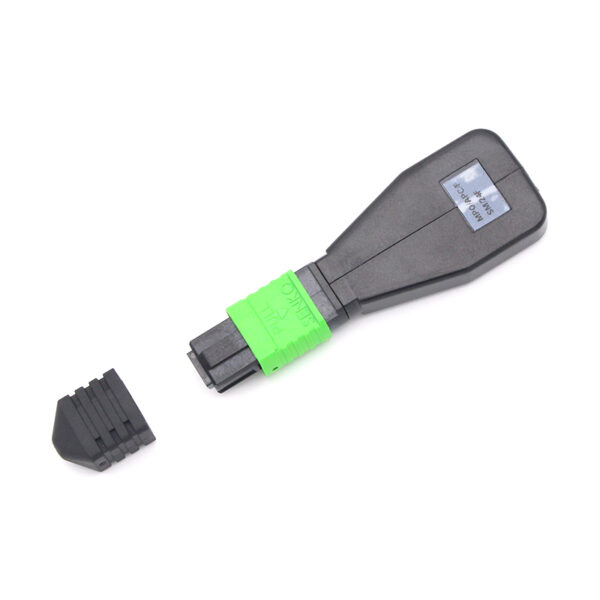
| Product Type | MPO Loopback Module |
| Fiber Count | 24 Fibers |
| Connector Type | MPO-24 (Female / Male available) |
| Connector Gender | Female (no guide pins) by default; Male (with guide pins) optional |
| Polish Type | SM: UPC or APC (8 deg angled); MM: UPC (flat) |
| Fiber Type | Singlemode OS2 (9/125 um) |
| Polarity | Type 1 (straight), Type 2 (crossed) or custom |
| Housing Material | LSZH (Low Smoke Zero Halogen) thermoplastic |
| Coupling Mechanism | Push-pull design |
| Dust Cap | Protective dust cap included |
| Guide Pin Diameter | 0.7 mm (male connector) |
| Ferrule Type | 24-fiber MT ferrule (6.4 mm x 2.5 mm ceramic) |
3.2 Optical Performance – Singlemode
| Parameter | Low Loss | Standard | Unit |
| Typical Insertion Loss | 0.35 | 0.50 | dB |
| Maximum Insertion Loss | 0.75 | 1.50 | dB |
| Return Loss (UPC) | >= 50 | >= 50 | dB |
| Return Loss (APC) | >= 60 | >= 60 | dB |
| Operating Wavelength | 1310 / 1550 | 1310 / 1550 | nm |
3.3 Optical Performance – Multimode
| Parameter | Low Loss | Standard | Unit |
| Typical Insertion Loss | 0.20 | 0.35 | dB |
| Maximum Insertion Loss | 0.60 | 1.00 | dB |
| Return Loss | >= 25 | >= 25 | dB |
| Operating Wavelength | 850 / 1300 | 850 / 1300 | nm |
3.4 Environmental Specifications
| Parameter | Specification |
| Operating Temperature | -40 degC to +75 degC |
| Storage Temperature | -40 degC to +85 degC |
| Humidity | 5% to 95% RH (non-condensing) |
| Altitude | Up to 3,000 m |
| Vibration | IEC 61300-2-1 compliant |
| Shock | IEC 61300-2-9 compliant |
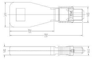
3.5 Dimension Specifications
4. Fiber Mapping & Polarity
The internal fiber mapping of the loopback module routes transmit (TX) lanes back to the corresponding receive (RX) lanes. The exact mapping depends on the selected polarity type and must match the target transceiver architecture.
The following polarity options are available:
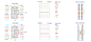
4.1 Typical 24-Fiber Mapping for 800G Applications
For 800G applications using MPO-24, the typical lane configuration uses 8 active fibers for TX and 8 for RX (with 8 fibers unused or reserved). Common mapping patterns include:
| Application | TX Lanes | RX Lanes | Unused Fibers |
| 100G-SR4 | Fibers 1-4 | Fibers 5-8 | Fibers 9-24 (unused) |
| 400G-SR8 | Fibers 1-8 | Fibers 13-20 | Fibers 9-12, 21-24 |
| 800G-DR8 | Fibers 1-8 | Fibers 13-20 | Fibers 9-12, 21-24 |
| 2x100G Split | Fibers 1-4, 13-16 | Fibers 5-8, 17-20 | Fibers 9-12, 21-24 |
Note: Always confirm the internal mapping drawing with the supplier before bulk procurement. Incorrect mapping can produce misleading test results or false failure reports during commissioning.
5. Standards & Compliance
| Standard | Description |
| IEC 61754-7 | Fibre optic connectors – MPO connector interface |
| TIA-604-5 | Fiber optic connector intermateability – MPO type |
| IEC 61300-2 | Basic test and measurement procedures for fiber optic interconnecting devices |
| IEC 61300-3-4 | Insertion loss and return loss measurement methods |
| IEC 61300-2-1 | Vibration test (sinusoidal) |
| IEC 61300-2-9 | Mechanical shock test |
| RoHS | Restriction of Hazardous Substances Directive (2011/65/EU) |
| REACH | Registration, Evaluation, Authorisation of Chemicals (EC 1907/2006) |
6. Applications
The 24F MPO Loopback Module is suitable for a wide range of test and verification scenarios:
| Application | Description |
| Transceiver Testing | Verify TX/RX functionality of 100G/400G/800G MPO-24 transceivers (QSFP28, QSFP-DD, OSFP) without building a full network link |
| Switch Port Commissioning | Validate MPO port behavior and signal integrity before live network patching in data center deployments |
| Burn-in / Aging Test | Provide continuous optical loopback for extended equipment reliability and stress testing in factory environments |
| Network Troubleshooting | Isolate equipment-side faults from cabling infrastructure issues during fault diagnosis and resolution |
| Lab Simulation | Create controlled test paths for parallel optics research, protocol validation, and system-level simulation |
| Factory QA / Acceptance | Support repeatable outgoing inspection and acceptance routines for optical equipment manufacturers |
| High-Speed Interconnect Testing | Validate 400G-SR8 and 800G-DR8 transceiver links that utilize the full 24-fiber MPO interface for lane-level diagnostics |
7. Ordering Information
To place an order or request a quotation, please specify the following parameters:
| Parameter | Options | Default |
| Fiber Count | 24 | 24 |
| Fiber Type | OS2 (SM), OM3 (MM), OM4 (MM), OM5 (MM) | OS2 |
| Connector Gender | Female, Male | Female |
| Polish Type | UPC, APC (SM only) | UPC |
| Polarity | Type A, Type B, Type C, Custom | Type A |
| Performance Grade | Standard, Low Loss | Standard |
| Labeling | Standard or custom label | Standard |
| Packaging | Individual bag, tray, bulk | Individual bag |
Part Number Example: MPO24-LB-[Fiber Type]-[Gender]-[Polish]-[Polarity]-[Grade]
Example: MPO24-LB-SM-F-UPC-A-STD = 24F MPO Loopback, Singlemode, Female, UPC polish, Type A polarity, Standard grade
8. Handling & Maintenance
- Always use the protective dust cap when the module is not in use to prevent end-face contamination.
- Inspect the MPO connector end-face with a fiber inspection scope (IEC 61300-3-35) before each insertion.
- Clean the connector end-face using an MPO-specific cleaning tool (dry or wet-dry method) if contamination is detected.
- Do not touch the ferrule end-face with bare fingers; skin oils degrade optical performance.
- Store in original packaging in a clean, dry environment within the specified storage temperature range.
- Avoid bending the fiber pigtail (if applicable) below the minimum bend radius of 30 mm.
- After 500 mating cycles, inspect and re-clean the connector before continued use.
- Ensure the mating adapter and transceiver port are free of dust and debris before insertion.
- Use an MPO-24 alignment key indicator to verify correct orientation (Key-Up / Key-Down) before mating