
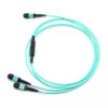
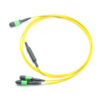
1x 24F MPO-2x12F MPO Conversion Cable
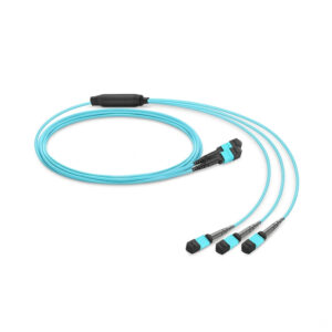
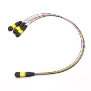
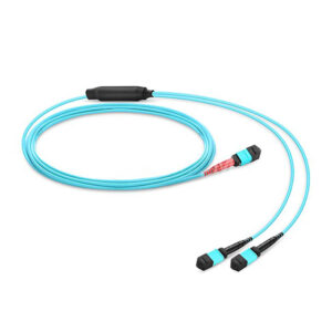
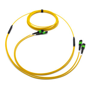
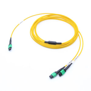
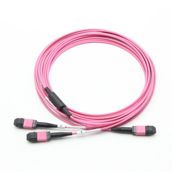
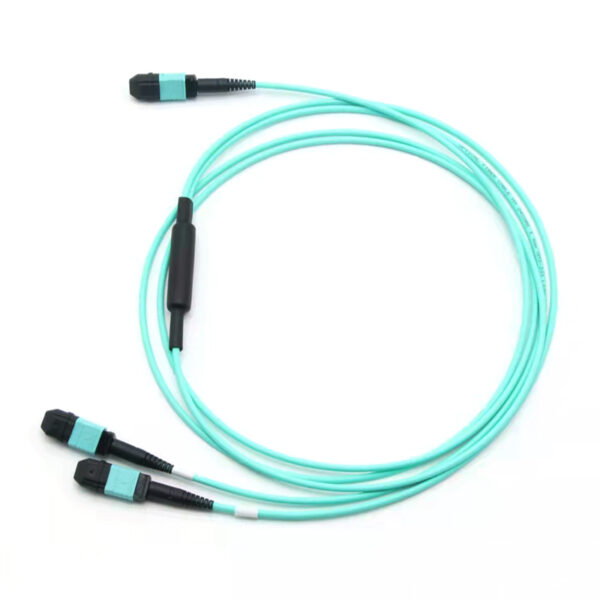
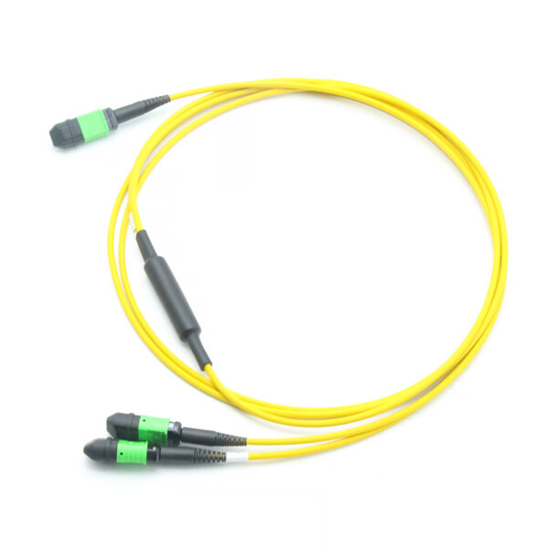
The 1 × 24-fiber MPO to 2 × 12-fiber MPO conversion cable is a factory-pre-terminated, plug-and-play multi-fiber breakout assembly. It presents one 24-position MPO connector on the trunk side and two 12-position MPO connectors on the branch side, converting a Base-24 parallel-optics infrastructure into two independent Base-12 links.
The assembly performs a purely physical fiber-count and fiber-position conversion. It contains no active components, no passive splitting elements and no wavelength-dependent devices — every one of the 24 trunk fibers is routed to exactly one branch fiber in a strict one-to-one relationship. Optical loss is therefore limited to connector insertion loss and cable attenuation only.
Share to:
Description
Why this product exists
Base-24 (24-fiber) structured cabling was widely deployed for 100GBASE-SR10 and for high-count trunk consolidation. Modern transceivers, however, are overwhelming Base-8 and Base-12 devices (40GBASE-SR4, 100GBASE-SR4, 100GBASE-DR/FR, 400GBASE-SR8). A Base-24 trunk feeding a Base-12 port leaves up to half of the installed fibers unused. This conversion cable recovers that stranded capacity:
| Infrastructure | Device interface | Fibers used without conversion | Fibers used with 1×24F → 2×12F |
| Base-24 trunk | 2 × Base-12 ports | not possible directly | 24 of 24 (100%) |
Optical Performance
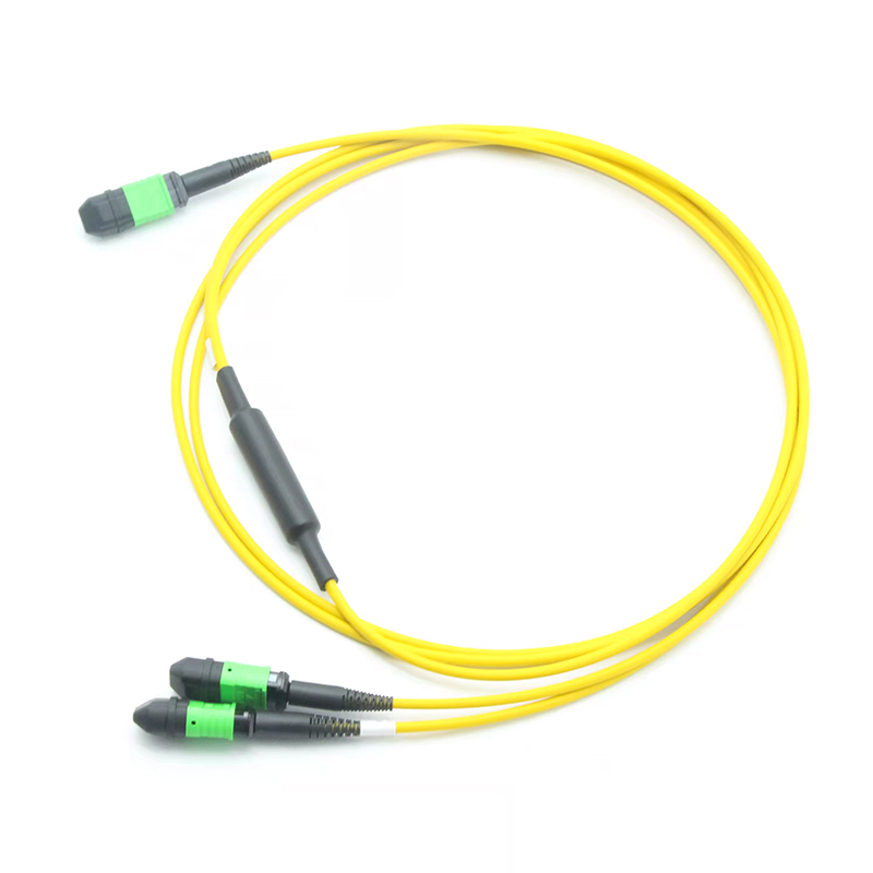
SM 1xMPO (24F Female) to 2x MPO (12F Female) Interconnect Conversion Harness Cable.
| Fiber Connector | 1xMPO to 2xMPO | Jacket OD | 3.0 mm |
| Fiber Category | 9/125μm SMF | Gender | Female to Female |
| Fiber Count | 24 | Test Wavelength | 1310nm |
| Insertion Loss | ≤0.75dB(stand MPO)
≤0.35dB(Super Low MPO) |
Return Loss | ≥60dB |
| Polarity | Type B (Full-Flipped) | Durability | ≥500 times |
| Operating temperature | -40 ~ 80°C | Fiber Grade | G657A1&G657A2 |
| Flame Rating | LSZH | Outer Jacket Color | Yellow |
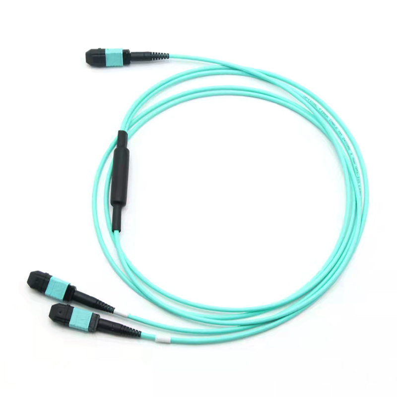
OM3 1xMPO (24F Female) to 2x MPO (12F Female) Interconnect Conversion Harness Cable.
| Fiber Connector | 1xMPO to 2xMPO | Jacket OD | 3.0 mm |
| Fiber Category | 50/125μm MM (OM3) | Gender | Female to Female |
| Fiber Count | 24 | Test Wavelength | 850nm |
| Insertion Loss | ≤0.60dB(stand MPO)
≤0.35dB(Super Low MPO) |
Return Loss | ≥20dB |
| Polarity | Type B (Full-Flipped) | Durability | ≥500 times |
| Operating temperature | -40 ~ 80°C | Fiber Grade | G651 |
| Flame Rating | LSZH | Outer Jacket Color | Aqua |
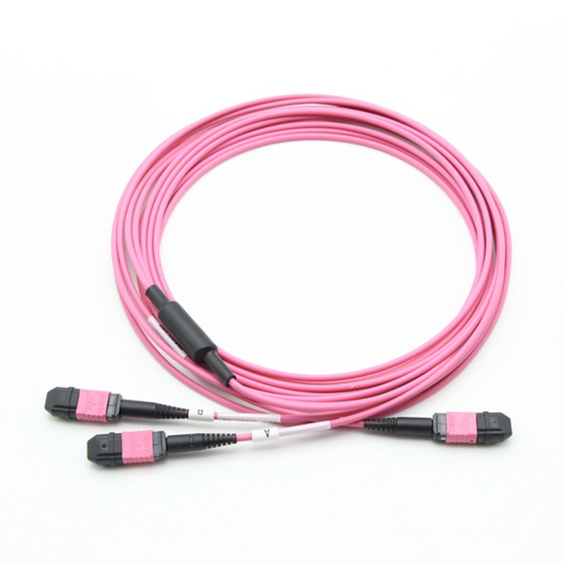
OM4 1xMPO (24F Female) to 2x MPO (12F Female) Interconnect Conversion Harness Cable.
| Fiber Connector | 1xMPO to 2xMPO | Jacket OD | 3.0 mm |
| Fiber Category | 50/125μm MM (OM4) | Gender | Female to Female |
| Fiber Count | 24 | Test Wavelength | 850nm |
| Insertion Loss | ≤0.60dB(stand MPO)
≤0.35dB(Super Low MPO) |
Return Loss | ≥20dB |
| Polarity | Type B (Full-Flipped) | Durability | ≥500 times |
| Operating temperature | -40 ~ 80°C | Fiber Grade | G651 |
| Flame Rating | LSZH | Outer Jacket Color | Magenta |
Cable Polarity
This assembly has three polarity-relevant ends, so polarity must be specified as a combination rather than a single label. The trunk end and the two branch ends may each be Type A or Type B, and the two branches are normally identical to each other for installation simplicity.
When the trunk end is Type A (straight):
Mapping follows Section 2.3 directly. Trunk 1–12 → Branch A 1–12; trunk 13–24 → Branch B 1–12.
When the trunk ends is Type B (reversed):
The 24-position sequence is inverted end-to-end, and because a 24-fiber ferrule is two stacked rows, the Consequently trunk positions 1–12 (row 1) emerge in reverse order on the branch carrying row 2, and trunk positions 13–24 (row 2) emerge in reverse order on the branch carrying row 1. The branch assignment therefore swaps relative to the Type A case, and each branch is itself reversed.
| Polarity | TYPE A (straight) | TYPE B (reversed) |
| Fiber Map | Trunk 1–12 ──► Branch A 1–12 | Trunk 1–12 ──► Branch A 12–1 |
| Fiber Map | Trunk 13–24 ──► Branch B 1–12 | Trunk 13–24 ──► Branch B 12–1 |
Features and Benefits
- 100% fiber utilization of existing Base-24 trunk cables — no re-cabling, no re-termination
- Zero-splice conversion — fully factory-terminated and 100% tested; no field fusion splicing required
- Push-pull MPO coupling — tool-free mating and de-mating, rapid deployment in congested panels
- Polarity-managed — available in TIA-568.3-D Method A, Method B and Method C configurations
- High-density — 24 fibers terminated in a single connector footprint identical to a 12-fiber MPO housing
- Low insertion loss — standard, low-loss and Super Low-grade MT ferrule options
- Flexible fiber types — OS2 single-mode, OM3 / OM4 / OM5 laser-optimized multimode
- Jacket options — LSZH, OFNP (plenum), OFNR (riser) and PVC to match local fire code
- Custom lengths and breakout legs — assembly length and branch-leg length are configurable
Application
1 Base-24 to Base-12 Infrastructure Migration
The primary use case. Data centers built in the 2010s commonly installed Base-24 trunk cabling and Base-24 patch panels to serve 100GBASE-SR10 and to maximize trunk fiber density. As those facilities upgrade to Base-8 and Base-12 transceivers, the installed Base-24 backbone becomes incompatible with new equipment ports.
This conversion cable bridges the two generations without touching the permanent infrastructure:
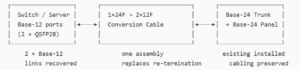
Benefit: avoids the cost, downtime and physical disruption of re-terminating or replacing installed trunk cables.
2 Doubling Port Density at the Equipment Face
One Base-24 trunk position, terminated into this cable, yields two independent Base-12 interfaces. At the equipment or patch-panel face these doubles the number of serviceable ports per trunk position — valuable in facilities where panel space and cable pathway fill are the binding constraints rather than fiber count.
3 Recovering Stranded Fibers in SR4 Deployments
A 40GBASE-SR4 or 100GBASE-SR4 transceiver uses 8 fibers of a 12-fiber MPO interface, leaving 4 positions unused. Connecting such a transceiver directly to a Base-24 trunk strands 16 of 24 fibers (67% waste). Inserting this conversion cable allows two SR4-class links to be served from a single Base-24 trunk position, using 16 of 24 fibers. Combining with additional Base-12-to-Base-8 conversion hardware can raise utilization further.
4 100GBASE-SR10 Breakout
Where legacy 100GBASE-SR10 endpoints remain in service alongside newer Base-12 equipment, this cable presents the SR10 row structure as two standard Base-12 interfaces, simplifying patching and enabling mixed-generation interoperability during phased migration.
5 Cross-Connect and Patch Panel Interworking
In structured main-distribution and horizontal-distribution areas, Base-24 and Base-12 cassettes, panels and trunks frequently coexist. This assembly serves as the standardized interworking element between the two counts, eliminating ad-hoc field solutions and the polarity errors they introduce.
6 Test Lab and Burn-In Environments
Test benches require frequent reconfiguration between 24-fiber test fixtures and 12-fiber instruments. A pre-terminated, pre-tested conversion cable provides repeatable, documented connectivity without field splicing, reducing setup time and eliminating splice-loss variability from measurement results.