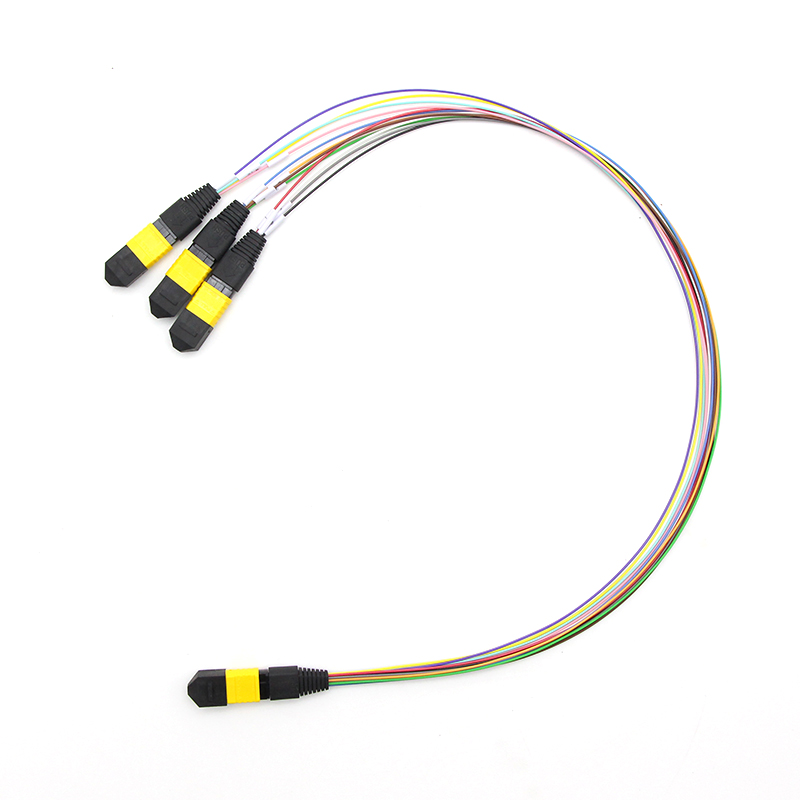

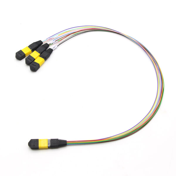
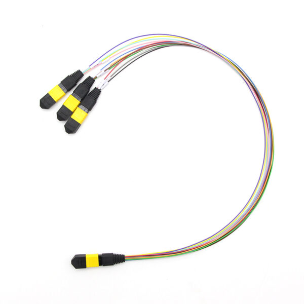
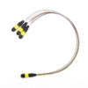
1x 24F MTP-3x8F MTP Conversion Cable

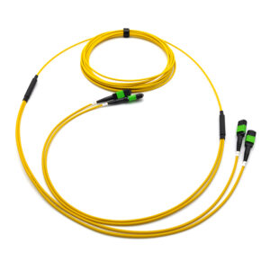
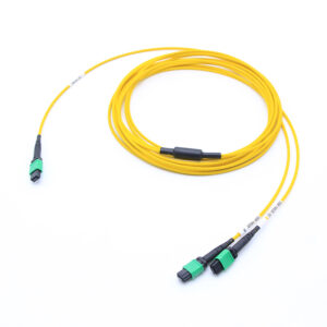
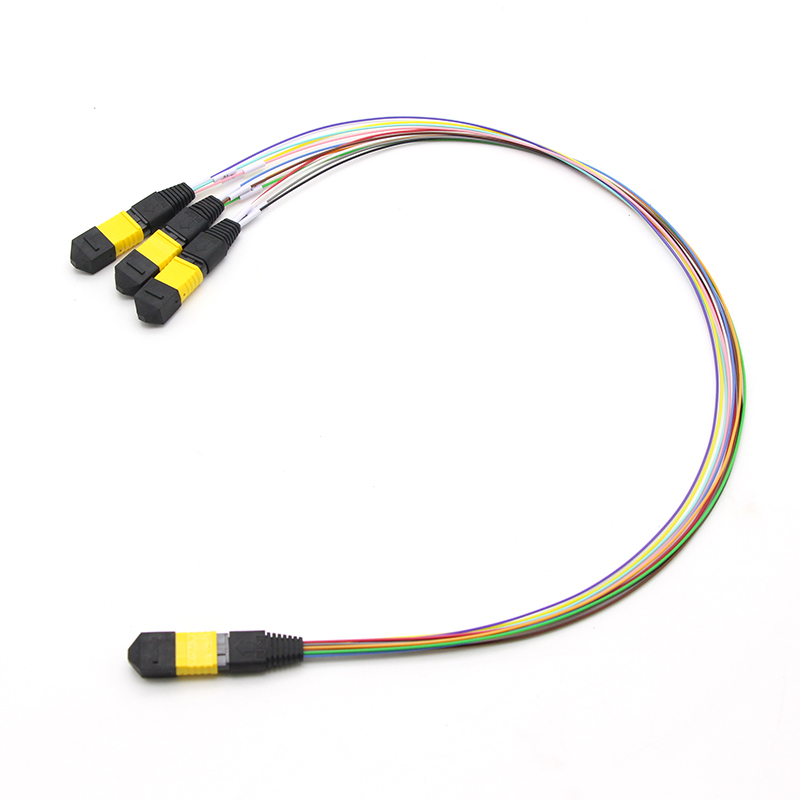
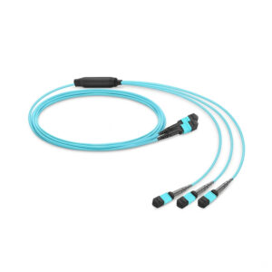
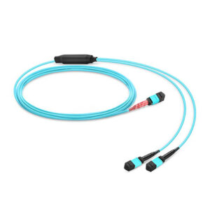
The 1 × 24-fiber MTP to 3 × 8-fiber MTP conversion cable is a factory-pre-terminated, plug-and-play multi-fiber breakout assembly. It presents one 24-position MTP connector on the trunk side and three 8-position MTP connectors on the branch side, converting a Base-24 parallel-optics infrastructure into three independent Base-8 links.

Because 24 is an exact multiple of 8, this conversion is arithmetically lossless: every trunk fiber is delivered to a branch fiber with zero unused positions on either side of the assembly. This is the defining advantage of Base-8 architecture and the reason this cable — rather than a 2 × 12-fiber variant — is the correct choice for SR4-class and modern parallel-optics deployments.

The assembly performs a purely physical fiber-count and fiber-position conversion. It contains no active components, no passive splitting elements and no wavelength-dependent devices. Each of the 24 trunk fibers is routed to exactly one branch fiber in a strict one-to-one relationship, so optical loss is limited to connector insertion loss and cable attenuation only.

Share to:

Description

Why this product exists

Base-24 (24-fiber) structured cabling was widely deployed for 100GBASE-SR10 and for high-count trunk consolidation. Modern transceivers, however, are overwhelmingly Base-8 and Base-16 devices — 40GBASE-SR4, 100GBASE-SR4, 200GBASE-SR4 and 400GBASE-SR8 all operate on groups of 8 fibers (4 Tx + 4 Rx per lane group). A Base-24 trunk feeding Base-12 hardware leaves a third of the installed fibers permanently dark. This conversion cable recovers that stranded capacity in full:

Infrastructure Device interface Fibers used Utilization
Base-24 trunk 3 × Base-8 ports (SR4, 8 active each) 24 of 24 100.00%

The 3 × 8-fiber configuration is the only arrangement of a 24-fiber trunk that fully feeds SR4-class transceivers with no dark fiber. Where the deployment is SR4-heavy — which describes most data centers — this cable delivers measurably more usable links per trunk position than any Base-12 alternative.


Optical Performance

Parameter Multimode (OM3/OM4/OM5) Single-mode (OS2)
Operating wavelength 850 nm / 1300 nm 1260–1650 nm
Test wavelength 850 nm and 1300 nm 1310 nm and 1550 nm
End-face polish PC / UPC (flat) APC (8° angled) standard; UPC optional
Insertion loss — Elite grade ≤ 0.20 dB [typ. max] ≤ 0.20 dB [typ. max]
Insertion loss — low-loss grade ≤ 0.35 dB [typ. max] ≤ 0.35 dB [typ. max]
Insertion loss — standard grade ≤ 0.50 dB [typ. max] ≤ 0.70 dB [typ. max]
Regulatory IL ceiling ≤ 0.75 dB per mated pair — ANSI/TIA-568.3-D maximum ≤ 0.75 dB per mated pair — ANSI/TIA-568.3-D maximum
Return loss ≥ 20 dB (PC); ≥ 35 dB (high-grade UPC) ≥ 50 dB (UPC); ≥ 60 dB (APC)
Repeatability ≤ 0.20 dB change over rated mating cycles ≤ 0.30 dB change over rated mating cycles
Interchangeability ≤ 0.20 dB (random mated pairs, Elite grade) ≤ 0.30 dB (random mated pairs)
Wavelength-dependent loss Not applicable at rated bands ≤ 0.10 dB across 1260–1650 nm


Connector &Cable Specification

Parameter Specification
Fiber count 12 + 12 = 24 (trunk side) → 8 + 8 + 8 = 24 (branch side)
Fiber arrangement at trunk Two independent single rows × 12 fibers, 0.25 mm pitch
Fiber arrangement at branches Three independent single rows × 8 fibers, 0.25 mm pitch
Fiber type — single-mode OS2, ITU-T G.652.D; G.657.A1 / A2 bend-insensitive optional
Fiber type — multimode OM3, OM4 or OM5 laser-optimized 50/125 µm, per IEC 60793-2-10
Ferrule type MT rectangular multi-fiber — 12-position (trunk) / 8-position (branches)
Connector count 5 total — 2 trunk + 3 branch
Trunk leg OD 2.0–3.0 mm per leg
Branch leg OD 2.0–3.0 mm per leg
Jacket material LSZH / OFNP / OFNR / PVC
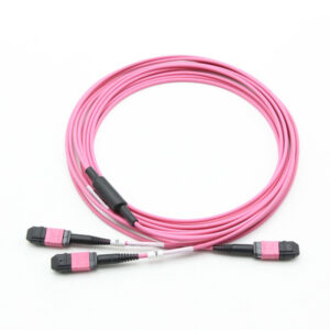
Jacket color SM Yellow, OM3 Aqua, OM4 Magenta or Customization


Cable Polarity

This assembly has four polarity-relevant ends, so polarity must be specified as a combination rather than a single label. The trunk end and the three branch ends may each be Type A or Type B; the three branches are normally identical to one another for installation simplicity.

   TYPE A (straight)                 TYPE B (reversed)
Trunk 1-8 -> Branch A 1->8 Trunk 1-8 -> Branch C 8->1
Trunk 9-16 -> Branch B 1->8 Trunk 9-16 -> Branch B 8->1
Trunk 17-24 -> Branch C 1->8 Trunk 17-24 -> Branch A 8->1


Features

  • 100% fiber utilization of existing Base-24 trunk cables — no dark fibers, no re-cabling, no re-termination
  • Three independent Base-8 links from a single trunk position — tripled port density at the equipment face
  • Lane-native SR4 alignment — each branch presents exactly 4 Tx + 4 Rx positions matching IEEE 802.3 parallel-optics PMDs
  • Zero-splice conversion — fully factory-terminated and 100% tested; no field fusion splicing required
  • Push-pull MTP coupling — tool-free mating and de-mating, rapid deployment in congested panels
  • Polarity-managed — available in TIA-568.3-D Method A and Method B configurations
  • Future-proof — Base-8 branches align with 16-fiber and 32-fiber 400G / 800G roadmaps
  • High-density — 24 fibers terminated in a single connector footprint identical to a 12-fiber MTP housing
  • Low insertion loss — standard, low-loss and Elite-grade MT ferrule options
  • Flexible fiber types — OS2 single-mode, OM3 / OM4 / OM5 laser-optimized multimode
  • Jacket options — LSZH, OFNP (plenum), OFNR (riser) and PVC to match local fire code
  • Custom lengths and breakout legs — assembly length and per-branch leg length are configurable

Application

1. Base-24 to Base-8 Infrastructure Migration

The primary use case. Data centers built in the 2010s commonly installed Base-24 trunk cabling and Base-24 patch panels to serve 100GBASE-SR10 and to maximize trunk fiber density. As those facilities upgrade to Base-8 transceivers, the installed Base-24 backbone becomes incompatible with new equipment ports, and — worse — feeding Base-12 hardware strands a third of every trunk.

This conversion cable bridges the two generations without touching the permanent infrastructure, at full fiber utilization:
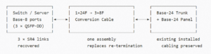
Fiber Utilization

Benefit: avoids the cost, downtime and physical disruption of re-terminating or replacing installed trunk cables, while delivering three usable links instead of two.


2. Tripling Port Density at the Equipment Face

One Base-24 trunk position, terminated into this cable, yields three independent Base-8 interfaces. At the equipment or patch-panel face this triples the number of serviceable ports per trunk position — valuable in facilities where panel space, cable pathway fill and tray capacity are the binding constraints rather than fiber count.


3. Speed Upgrade on Existing Cabling

Because each branch is a lane-complete 4-Tx + 4-Rx interface, the same assembly supports successive generations of SR4-class optics without change:

Generation Per-branch link Aggregate from one trunk position
40GBASE-SR4 40 Gb/s 120 Gb/s
100GBASE-SR4 100 Gb/s 300 Gb/s
200GBASE-SR4 200 Gb/s 600 Gb/s
400GBASE-SR4 400 Gb/s 1.2 Tb/s

A plant installed for 100GBASE-SR10 can therefore be re-purposed to carry three independent 400G links by swapping transceivers alone. No cabling work is required — which is the strongest commercial argument for this product.


4. AI and HPC Fabric Consolidation

AI training clusters and HPC fabrics are dense, short-reach, parallel-optics environments that consume very large numbers of 8-fiber links per rack. Converting Base-24 trunks to 3 × Base-8 maximizes the link count per pathway and per panel position, directly increasing the number of GPU-to-switch or node-to-node connections achievable within an existing cable tray footprint.


5. 100GBASE-SR10 Legacy Breakout

Where legacy 100GBASE-SR10 endpoints remain in service, the Base-24 trunk carries 20 active fibers across two rows. This cable presents that structure as three standard Base-8 interfaces, simplifying patching and enabling mixed-generation interoperability during phased migration. Positions beyond the SR10 lane count can be provisioned for growth.


6. Cross-Connect and Patch Panel Interworking

In structured main-distribution and horizontal-distribution areas, Base-24 and Base-8 cassettes, panels and trunks frequently coexist. This assembly serves as the standardized interworking element between the two counts, eliminating ad-hoc field solutions and the polarity errors they introduce.


7. Test Lab and Burn-In Environments

Test benches require frequent reconfiguration between 24-fiber test fixtures and 8-fiber instruments. A pre-terminated, pre-tested conversion cable provides repeatable, documented connectivity without field splicing, reduces setup time, and eliminates splice-loss variability from measurement results. Three instruments can share one fixture position.
 

Free Quote

Scroll to Top

Contact Us