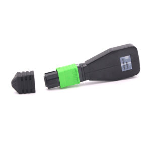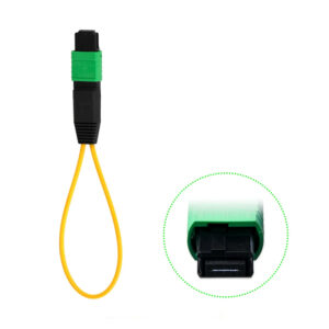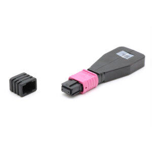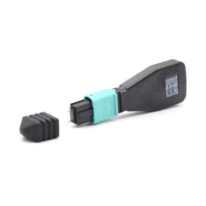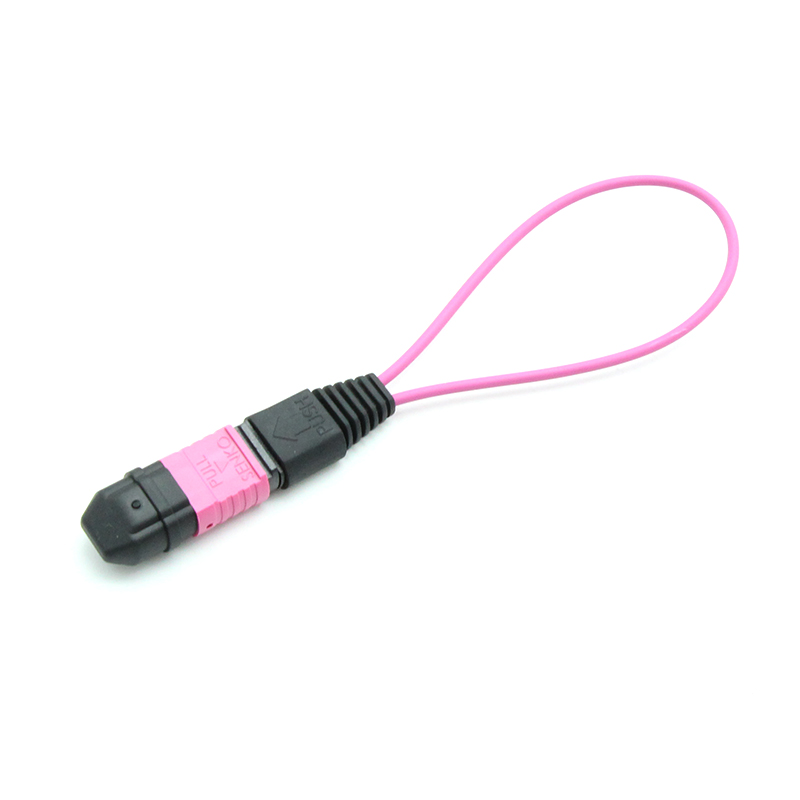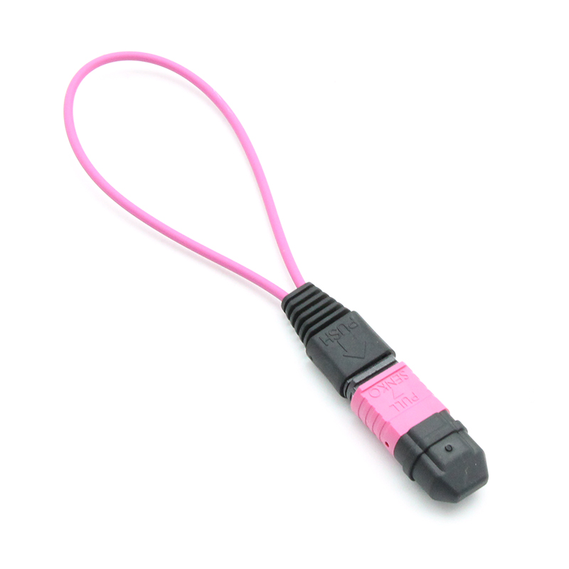

Key Features
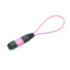
- 24-fiber MPO connector optimized for 400G/800G high-density parallel optics
- Laser-optimized OM4 50/125 um multimode fiber with 4700 MHz-km EMB at 850 nm
- Extended reach capability: 100G-SR4 up to 150m, 400G-SR8 up to 100m per IEEE 802.3
- UPC flat polish with 24-fiber MT ferrule for optimal multimode performance
- Push-pull coupling mechanism with enhanced retention for high-density panels
- Ultra-low insertion loss (<= 0.50 dB max, low-loss grade) for precise test accuracy
- High return loss (>= 30 dB typical) for clean signal reflection and minimal back-reflection
- Configurable polarity: Type A, Type B, Type C, or custom mapping for 24-lane architectures
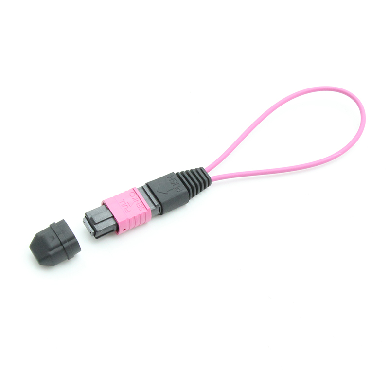
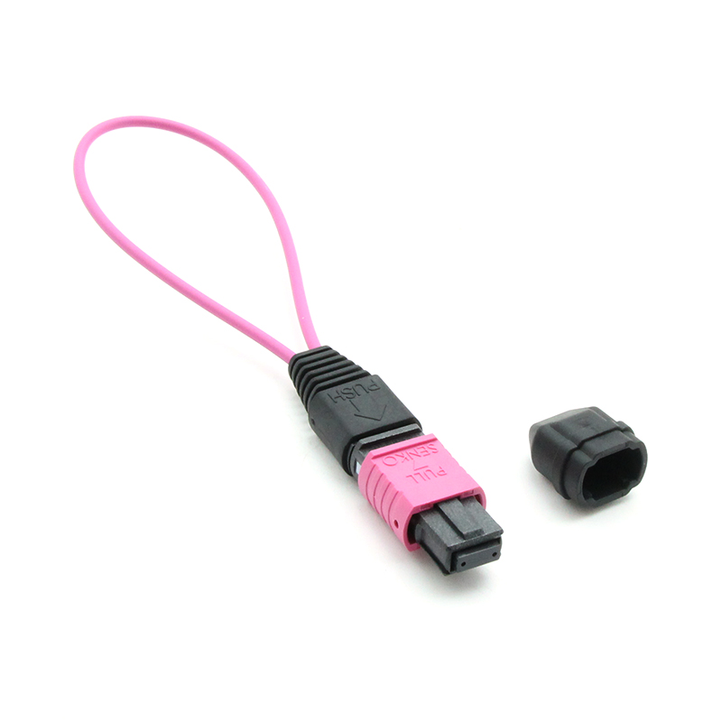
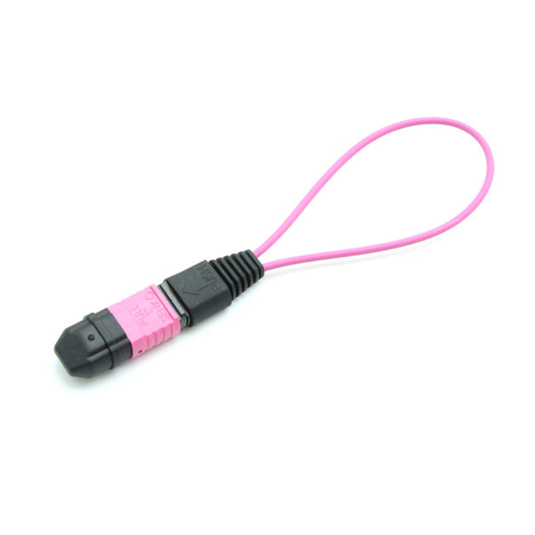
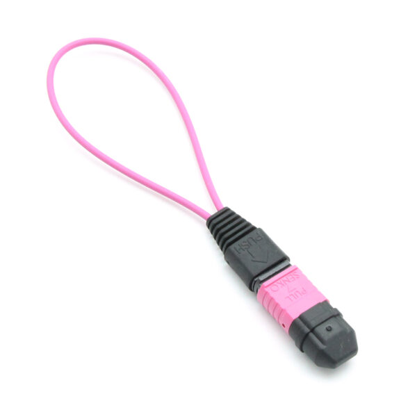
- Erika Violet connector shell per TIA-598-C for immediate OM4 multimode identification
- LSZH (Low Smoke Zero Halogen) housing with UL 94 V-0 flammability rating
- Dual-row MT ferrule design (2×12) for compact 24-fiber integration
- Compatible with QSFP-DD, OSFP, CFP8, and next-generation 800G transceiver platforms
- Backward compatible with OM3 infrastructure for mixed-fiber environment testing
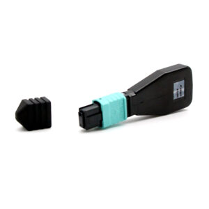
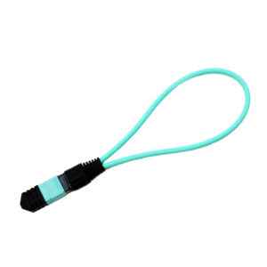
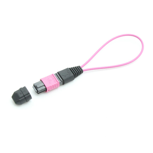
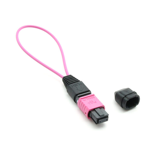
- Protective dust cap with tether option for field deployment and loss prevention
- RoHS and REACH compliant with full material traceability
Technical Specifications
1、General Parameters
| Parameter | Specification |
| Product Type | MPO Loopback Module (High-Density Multimode) |
| Fiber Count | 24 Fibers (2×12 dual-row MT ferrule) |
| Fiber Type | OM4 Multimode 50/125 um (laser-optimized, IEC 60793-2-10 A1a.3) |
| Connector Type | MPO-24 (Female / Male available) |
| Connector Gender | Female (no guide pins) standard; Male (with guide pins) optional |
| Connector Shell Color | Erika Violet (OM4 identification per TIA-598-C) |
| Polish Type | UPC (Ultra Physical Contact, flat polish) |
| Polarity | Type A, Type B, Type C, or custom mapping per 24-lane architecture |
| Housing Material | LSZH (Low Smoke Zero Halogen) thermoplastic, UL 94 V-0 rated |
| Coupling Mechanism | Enhanced push-pull design with positive retention |
| Dust Cap | Protective dust cap included; tethered cap optional |
| Guide Pin Diameter | 0.7 mm (male connector), dual guide pins |
| Ferrule Type | 24-fiber MT ferrule (6.4 mm x 2.5 mm, dual-row ceramic) |
| Weight (typical) | 8 g per module (without pigtail) |
| Dimensions (L x W x H) | 52 mm x 12 mm x 8 mm (typical) |
2、Optical Performance
| Parameter | Low Loss Grade | Standard Grade | Unit |
| Typical Insertion Loss | 0.15 | 0.25 | dB |
| Maximum Insertion Loss | 0.50 | 0.75 | dB |
| Return Loss | >= 30 | >= 25 | dB |
| Operating Wavelength | 850 / 1300 | 850 / 1300 | nm |
| Lane-to-Lane Uniformity | <= 0.2 | <= 0.3 | dB |
| Cross-Talk Isolation | >= 60 | >= 50 | dB |
3、OM4 Fiber Characteristics
| Parameter | Specification |
| Core / Cladding Diameter | 50.0 +/- 2.5 / 125.0 +/- 1.0 um |
| Effective Modal Bandwidth (EMB) @ 850 nm | >= 4700 MHz-km |
| Overfilled Launch Bandwidth @ 850 nm | >= 3500 MHz-km |
| Overfilled Launch Bandwidth @ 1300 nm | >= 500 MHz-km |
| Maximum Attenuation @ 850 nm | 3.0 dB/km |
| Maximum Attenuation @ 1300 nm | 1.0 dB/km |
| Differential Mode Delay (DMD) | Per IEC 60793-1-49 |
| Numerical Aperture (NA) | 0.20 +/- 0.015 |
| Macro-bend Loss @ 850 nm (7.5 mm, 2 turns) | <= 0.5 dB |
| Jacket Color | Erika Violet (per TIA-598-C) |
| Minimum Bend Radius (short-term) | 30 mm |
| Minimum Bend Radius (long-term) | 15 mm |
| Fiber Count per Row | 12 fibers (2 rows of 12) |
4、Transmission Distance Capability
The following table lists maximum supported transmission distances for high-speed transceiver types when using OM4 fiber, providing design context for test environments:
| Transceiver Type | Data Rate | Max Distance (OM4) | Active Fibers | Modulation |
| 40G-SR4 (QSFP+) | 40 Gbps | 150 m | 8 (4 TX + 4 RX) | NRZ |
| 100G-SR4 (QSFP28) | 100 Gbps | 150 m | 8 (4 TX + 4 RX) | NRZ |
| 200G-SR4 (QSFP56) | 200 Gbps | 100 m | 8 (4 TX + 4 RX) | PAM4 |
| 400G-SR8 (QSFP-DD) | 400 Gbps | 100 m | 16 (8 TX + 8 RX) | PAM4 |
| 400G-SR4.2 (QSFP-DD) | 400 Gbps | 150 m | 8 (4 TX + 4 RX) | PAM4 |
| 800G-SR8 (QSFP-DD800) | 800 Gbps | 50 m | 16 (8 TX + 8 RX) | PAM4 |
| 800G-2xSR4 (OSFP) | 800 Gbps | 100 m | 16 (2×4 TX + 2×4 RX) | PAM4 |
5、Environmental Specifications
| Parameter | Specification |
| Operating Temperature | -40 degC to +75 degC (extended range) |
| Storage Temperature | -40 degC to +85 degC |
| Thermal Shock | -40 degC to +75 degC, 50 cycles per IEC 61300-2-14 |
| Temperature-Humidity Bias | 85 degC / 85% RH, 2000 hours per IEC 61300-2-18 |
| Humidity (operating) | 5% to 95% RH (non-condensing) |
| Altitude | Up to 5,000 m (high-altitude data center support) |
| Salt Spray | IEC 61300-2-25 compliant (coastal deployment ready) |
| Industrial Atmosphere | IEC 61300-2-40 (SO2, H2S resistance) |
6、Mechanical Specifications
| Parameter | Specification |
| Mating Cycles | >= 1000 (enhanced durability for high-use environments) |
| Insertion Force | 15 – 25 N (24-fiber configuration) |
| Ferrule Compression Force | 20.0 – 25.0 N (dual-row ferrule) |
| Adapter Lock Travel | >= 2.5 mm |
| Maximum Extraction Force | 50.0 N |
| Tensile Strength (cable) | >= 200 N (reinforced for 24-fiber cables) |
| Vibration (operational) | IEC 61300-2-1, 10-2000 Hz, 3g (seismic rated) |
| Mechanical Shock | IEC 61300-2-9, 100g, 6 ms half-sine |
| Static Load | IEC 61300-2-5, 100 N for 1 minute |
| Cable Retention | IEC 61300-2-5, 150 N axial pull for 1 minute |
Fiber Mapping & Polarity
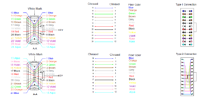
The 24-fiber configuration enables flexible mapping strategies to accommodate diverse high-speed transceiver architectures. Correct fiber mapping is essential for valid loopback diagnostics and must be matched to the target system architecture.
1、Available Polarity Options
2、24-Fiber Active Lane Configurations
Different transceiver platforms utilize varying numbers of active fibers from the 24-fiber MPO connector. The following table shows common configurations:
| Application | TX Lanes | RX Lanes | Unused Fibers | Notes |
| 400G-SR8 (QSFP-DD) | 1-8 | 17-24 | 9-16 | Full 8-lane active |
| 800G-SR8 (QSFP-DD800) | 1-8 | 17-24 | 9-16 | 8-lane PAM4 @ 100G/lane |
| 2x 100G-SR4 | 1-4, 13-16 | 9-12, 21-24 | 5-8, 17-20 | Dual transceiver |
| 2x 40G-SR4 | 1-4, 13-16 | 9-12, 21-24 | 5-8, 17-20 | Legacy equipment |
| 800G-2xSR4 (OSFP) | 1-4, 13-16 | 5-8, 17-20 | 9-12, 21-24 | Split-mode OSFP |
| 400G-SR4.2 | 1-4 | 9-12 | 5-8, 13-24 | 200G/lane PAM4 |
3、Dual-Row Ferrule Pinout Reference
The 24-fiber MPO connector uses a dual-row MT ferrule with 12 fibers in Row A (positions 1-12) and 12 fibers in Row B (positions 13-24). The connector features dual guide pins for enhanced alignment and stability.
| Row | Fiber Positions | Typical Assignment | Key Orientation |
| Row A | 1, 2, 3, 4, 5, 6, 7, 8, 9, 10, 11, 12 | Transmit lanes or first transceiver | Key-Up |
| Row B | 13, 14, 15, 16, 17, 18, 19, 20, 21, 22, 23, 24 | Receive lanes or second transceiver | Key-Up |
Critical: For 400G/800G applications, verify the exact lane mapping with the transceiver vendor documentation. Incorrect mapping will result in invalid test results and potential equipment damage. Always request and approve the internal mapping drawing before bulk procurement.
Advanced Testing Capabilities
The 24F OM4 MPO Loopback Module enables advanced testing scenarios beyond basic port verification, supporting complex validation workflows in modern data centers:
| Test Scenario | Description | Benefit |
| Multi-Port Simultaneous Test | Verify multiple transceiver ports in parallel using a single 24-fiber loopback module with split-mode mapping | Reduces test time by 50-75% |
| BER Threshold Validation | Establish baseline bit-error-rate performance for each lane under controlled loopback conditions | Ensures link margin compliance |
| Power Level Calibration | Measure and equalize optical power levels across all active lanes for balanced system performance | Optimizes SNR and reach |
| Temperature Sweep Testing | Validate transceiver performance across temperature range using loopback in environmental chamber | Confirms operational stability |
| Polarization Mode Dispersion | Characterize PMD effects in multimode links using loopback configuration with PMD test equipment | Validates signal integrity |
| Eye Diagram Analysis | Capture and analyze eye diagrams for each lane under loopback to verify modulation quality and timing margins | Ensures protocol compliance |
Transceiver Compatibility Matrix
Comprehensive compatibility with current and next-generation transceiver platforms:
| Form Factor | Interface | Data Rate | Fibers Used | Compatibility |
| QSFP+ | MPO-12 | 40 Gbps | 8 | Direct (native) |
| QSFP28 | MPO-12 | 100 Gbps | 8 | Direct (native) |
| QSFP56 | MPO-12 | 200 Gbps | 8 | Direct (native) |
| QSFP-DD | MPO-24 | 400 Gbps | 16 | Direct (SR8) |
| QSFP-DD800 | MPO-24 | 800 Gbps | 16 | Direct (SR8) |
| OSFP | MPO-24 | 800 Gbps | 16 | Direct (2xSR4) |
| CFP8 | MPO-24 | 400 Gbps | 16 | Direct (native) |
| CXP | MPO-12 x2 | 120 Gbps | 20 | Dual MPO-12 |
Applications
The 24F OM4 MPO Loopback Module addresses advanced testing requirements across high-performance computing, hyperscale data centers, and emerging 800G deployments:
| Application | Description | Target Environment |
| 400G Transceiver Validation | Full 8-lane TX/RX verification for 400G-SR8 QSFP-DD transceivers with lane-level power and BER diagnostics | Hyperscale Data Center |
| 800G System Testing | Dual 12-fiber or 16-fiber active lane testing for 800G-SR8 and 800G-DR8 transceiver platforms | AI/HPC Cluster |
| AI Fabric Validation | Comprehensive port verification for GPU-to-switch interconnects in AI training clusters using 400G/800G parallel optics | AI Training Infrastructure |
| Switch Spine Commissioning | High-density MPO port validation in spine-leaf architectures before live network deployment | Data Center Fabric |
| Equipment Burn-in | Continuous 24-lane optical loopback for extended reliability testing during factory acceptance procedures | Manufacturing QA |
| Multi-Port Diagnostics | Simultaneous testing of dual 12-fiber transceiver pairs or split-mode configurations | Lab/Test Environment |
| Mixed OM3/OM4 Testing | Backward compatibility validation and performance margin assessment in mixed-fiber plant environments | Brownfield Deployment |
| High-Density Panel Testing | Rapid verification of 24-fiber MPO cassettes and patch panels in high-density fiber distribution frames | Structured Cabling |
Ordering Information
To place an order or request a quotation, please specify the following parameters:
| Parameter | Options | Default |
| Fiber Count | 24 | 24 |
| Fiber Type | OM4 (50/125 um, laser-optimized multimode) | OM4 |
| Connector Gender | Female (standard), Male (optional) | Female |
| Polish Type | UPC | UPC |
| Polarity | Type A, Type B, Type C, Type D, Custom (per drawing) | Type A |
| Performance Grade | Low Loss, Standard | Standard |
| Dust Cap | Standard (loose), Tethered (attached) | Standard |
| Labeling | Standard, Custom (laser-etched or printed) | Standard |
| Packaging | Individual anti-static bag, foam tray, bulk carton | Individual bag |
| Minimum Order Quantity | 1 pc (sample); 5 pcs (production) | 1 pc |
| Lead Time | Standard: 2-3 weeks; Custom mapping: 3-4 weeks | N/A |
Part Number Convention: MPO24-LB-OM4-[Gender]-[Polish]-[Polarity]-[Grade]-[Options]
Example: MPO24-LB-OM4-F-UPC-A-STD = 24F OM4 MPO Loopback, Female, UPC polish, Type A polarity, Standard grade
Example: MPO24-LB-OM4-F-UPC-D-LL-T = 24F OM4 MPO Loopback, Female, UPC polish, Type D (8+8+8 split) polarity, Low Loss grade, tethered cap
Standards & Compliance
| Standard | Description |
| IEC 61754-7 | Fibre optic connectors – MPO connector interface standard |
| IEC 60793-2-10 | Optical fibres – Product specifications – A1a.3 (OM4) |
| TIA-492AAAD | OM4 multimode fiber specification (50/125 um, laser-optimized) |
| TIA-598-C | Optical fiber cable color coding and identification |
| TIA-604-5 | Fiber optic connector intermateability – MPO type |
| ISO/IEC 11801 | Generic cabling for customer premises (OM4 class) |
| IEEE 802.3cm | 400 Gb/s Ethernet over multimode fiber |
| IEEE 802.3df | 800 Gb/s Ethernet over multimode fiber (draft) |
| IEC 61300-2-x | Basic test procedures: vibration, shock, thermal, humidity, static load |
| IEC 61300-3-4 | Attenuation / insertion loss measurement method |
| IEC 61300-3-35 | Visual inspection of fiber optic connector end-faces |
| GR-326-CORE | Generic requirements for single-mode optical connectors (reference) |
| UL 94 V-0 | Flammability rating for housing material |
| RoHS 2011/65/EU | Restriction of Hazardous Substances Directive |
| REACH EC 1907/2006 | Registration, Evaluation, Authorisation of Chemicals |
Handling, Storage & Maintenance
1、Handling Precautions
- Always use the protective dust cap when the module is not mated to prevent end-face contamination. The 24-fiber ferrule is particularly susceptible to contamination due to high fiber density.
- Inspect the MPO connector end-face with a fiber inspection microscope (per IEC 61300-3-35) before each insertion. Use 200x magnification minimum for 24-fiber inspection. Reject modules with visible scratches, pits, or contamination.
- Clean the connector end-face using an MPO-24 specific cleaning tool (cassette cleaner or click cleaner designed for 24-fiber connectors). Standard 12-fiber cleaners may not cover all fibers.
- Do not touch the ferrule end-face with bare fingers. Skin oils degrade optical performance and can cause permanent end-face damage, especially critical on high-density 24-fiber ferrules.
- Verify the Erika Violet shell color matches the target OM4 multimode adapter. Do not mate OM4 connectors with singlemode (yellow/black) or OM1/OM2 (orange/beige) infrastructure.
- Align both guide pins and keying notch correctly before insertion. The 24-fiber connector requires precise alignment due to dual-row ferrule design.
- Use anti-static handling procedures in ESD-sensitive environments. The MPO connector housing can accumulate static charge.
2、Storage Requirements
- Store in original anti-static packaging in a clean, dry, temperature-controlled environment (Class 10000 or better recommended).
- Maintain storage temperature between -40 degC and +85 degC. Avoid rapid temperature changes that may cause condensation.
- Maintain humidity below 85% RH during storage to prevent moisture absorption in the ferrule material.
- Avoid exposure to direct sunlight, UV radiation, and corrosive atmospheres (H2S, SO2, chlorine) during storage.
- Do not stack more than 10 modules vertically to prevent housing deformation and guide pin damage.
- Store in original packaging until ready for use. Do not remove dust caps until immediately before mating.
3、Maintenance Schedule
| Condition | Action Required | Frequency |
| Before each use | Visual inspection with 200x microscope; clean if contamination detected | Every use |
| After 100 mating cycles | Detailed end-face inspection per IEC 61300-3-35 Grade B; document results | Periodic |
| After 500 mating cycles | Full inspection; measure insertion loss; re-polish if degradation observed | Scheduled |
| After 1000 mating cycles | Comprehensive inspection; consider replacement if out of specification | End-of-life assessment |
| Annual (if stored) | Visual inspection; verify dust cap integrity; check for housing discoloration or degradation | Annual |
| After field incident | Immediate inspection; test insertion loss on all 24 lanes; replace if any lane out of spec | As needed |
4、Cleaning Procedures
Proper cleaning is critical for 24-fiber MPO connectors due to the high fiber density and reduced fiber pitch (250 um spacing). Follow these procedures:
| Method | Procedure | When to Use |
| Cassette Cleaner | Insert connector into MPO-24 cassette cleaner; advance tape; repeat 2-3 times if heavy contamination | Routine cleaning before each mating |
| Click Cleaner | Press connector into MPO-24 click cleaner until audible click; rotate 180 degrees and repeat | Field cleaning; quick maintenance |
| Wet-Dry Wipe | Apply 99% IPA to lint-free wipe; gently wipe ferrule end-face; dry with clean section of wipe | Heavy contamination; stubborn particles |
| Compressed Air | Use filtered, dry compressed air (oil-free) to blow loose particles; do not use as primary cleaning method | Supplemental to mechanical cleaning |
Revision History
| Revision | Date | Author | Description |
| Rev A | 2026-09-08 | Engineering | Initial release |
Disclaimer
This specification is subject to change without prior notice. The information contained herein is believed to be accurate and reliable at the time of publication. However, no warranty, expressed or implied, is made regarding the accuracy or completeness of the data. No liability is assumed for consequences of use, nor for any infringement of patents or other rights of third parties that may result from its use. All specifications represent typical values measured under controlled laboratory conditions unless otherwise noted. Actual performance may vary depending on installation environment, mating components, and operational conditions. The 24-fiber configuration requires particular attention to cleanliness and alignment due to high fiber density.