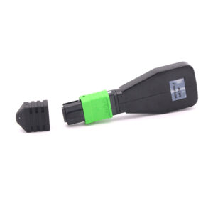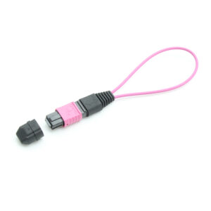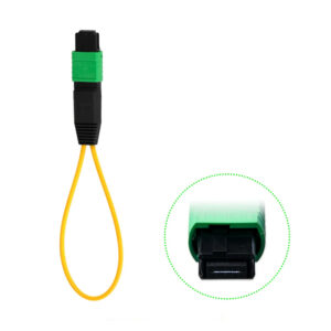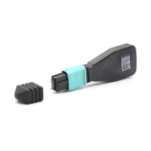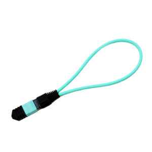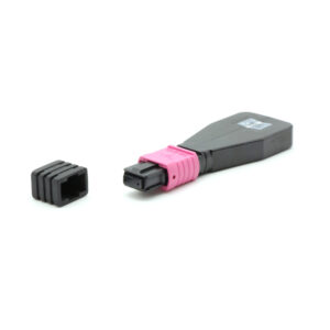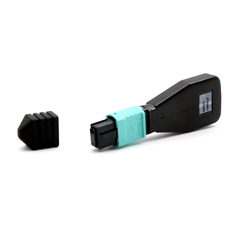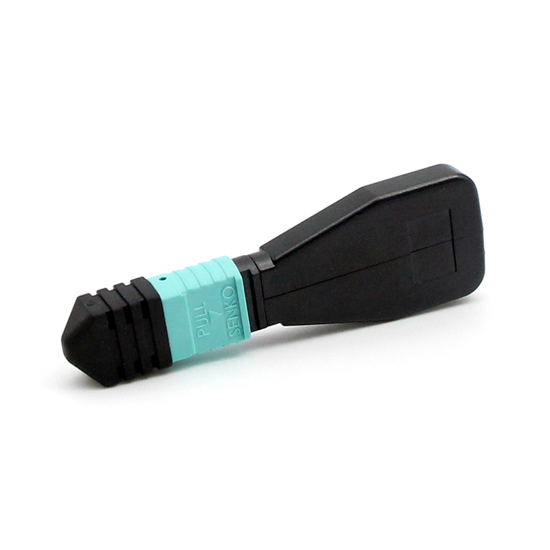

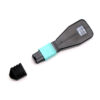
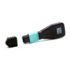
2. Key Features
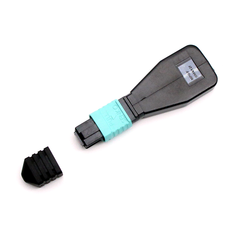
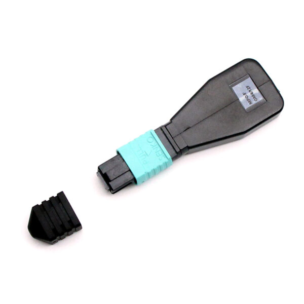
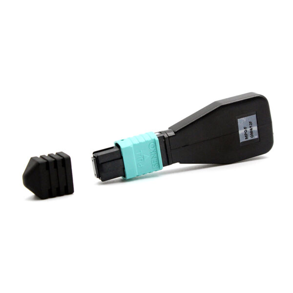
- 12-fiber MPO connector optimized for 40G/100G parallel optics architectures
- Laser-optimized OM3 50/125 um multimode fiber (per IEC 60793-2-10 A1a.2)
- Effective modal bandwidth: 2000 MHz-km at 850 nm
- UPC flat polish with precision MT ferrule for optimal multimode optical performance
- Push-pull coupling mechanism for tool-free insertion and extraction
- Low insertion loss (<= 1.00 dB max) for reliable multimode test accuracy
- High return loss (>= 25 dB typical) for clean signal reflection
- Configurable polarity: Type A, Type B, Type C, or custom mapping
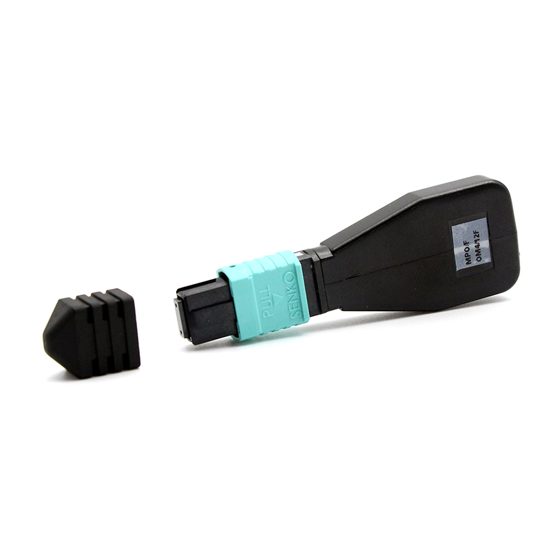
- Aqua-colored MPO connector shell for immediate multimode identification per TIA-598-C
- LSZH (Low Smoke Zero Halogen) housing for enhanced fire safety compliance
- Compatible with QSFP+, QSFP28, CXP, and CFP2 transceiver interfaces
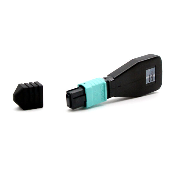
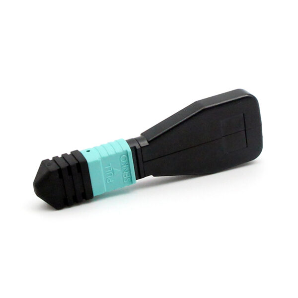
- Protective dust cap included for end-face contamination prevention
- RoHS and REACH compliant materials throughout
3. Technical Specifications
3.1 General Parameters
| Parameter | Specification |
| Product Type | MPO Loopback Module (Multimode) |
| Fiber Count | 12 Fibers |
| Fiber Type | OM3 Multimode 50/125 um (laser-optimized, per IEC 60793-2-10 A1a.2) |
| Connector Type | MPO-12 (Female / Male available) |
| Connector Gender | Female (no guide pins) by default; Male (with guide pins) optional |
| Connector Shell Color | Aqua (multimode identification per TIA-598-C) |
| Polish Type | UPC (Ultra Physical Contact, flat polish) |
| Coupling Mechanism | Push-pull design |
| Dust Cap | Protective dust cap included |
| Guide Pin Diameter | 0.7 mm (male connector) |
| Ferrule Type | 12-fiber MT ferrule (6.4 mm x 2.5 mm ceramic) |
| Weight (typical) | < 5 g per module (without pigtail) |
3.2 Optical Performance
| Parameter | Low Loss | Standard | Unit |
| Typical Insertion Loss | 0.20 | 0.35 | dB |
| Maximum Insertion Loss | 0.60 | 1.00 | dB |
| Return Loss | >= 30 | >= 25 | dB |
| Operating Wavelength | 850 / 1300 | 850 / 1300 | nm |
3.3 OM3 Fiber Characteristics
| Parameter | Specification |
| Core / Cladding Diameter | 50.0 +/- 2.5 / 125.0 +/- 1.0 um |
| Effective Modal Bandwidth (EMB) @ 850 nm | >= 2000 MHz-km |
| Overfilled Launch Bandwidth @ 850 nm | >= 1500 MHz-km |
| Overfilled Launch Bandwidth @ 1300 nm | >= 500 MHz-km |
| Maximum Attenuation @ 850 nm | 3.5 dB/km |
| Maximum Attenuation @ 1300 nm | 1.5 dB/km |
| Differential Mode Delay (DMD) | Per IEC 60793-1-49 |
| Numerical Aperture (NA) | 0.20 +/- 0.015 |
| Macro-bend Loss @ 850 nm (15 mm, 2 turns) | <= 0.5 dB |
| Jacket Color | Aqua (per TIA-598-C standard) |
| Minimum Bend Radius (short-term) | 30 mm |
| Minimum Bend Radius (long-term) | 15 mm |
3.4 Transmission Distance Capability
The following table lists the maximum supported transmission distances for common transceiver types when using OM3 fiber, providing context for test environment design and link budget verification:
| Transceiver Type | Data Rate | Max Distance (OM3) | Fibers Used |
| 10GBASE-SR (SFP+) | 10 Gbps | 300 m | 2 (duplex) |
| 40G-SR4 (QSFP+) | 40 Gbps | 100 m | 8 (4 TX + 4 RX) |
| 100G-SR4 (QSFP28) | 100 Gbps | 100 m | 8 (4 TX + 4 RX) |
| 100G-SR10 (CXP) | 100 Gbps | 100 m | 20 (10 TX + 10 RX) |
| 200G-SR4 (QSFP56) | 200 Gbps | 70 m | 8 (4 TX + 4 RX) |
3.5 Environmental Specifications
| Parameter | Specification |
| Operating Temperature | -40 degC to +75 degC |
| Storage Temperature | -40 degC to +85 degC |
| Thermal Shock | -40 degC to +75 degC, 20 cycles per IEC 61300-2-14 |
| Damp Heat (steady state) | 85 degC / 85% RH, 1000 hours per IEC 61300-2-18 |
| Humidity (operating) | 5% to 95% RH (non-condensing) |
| Altitude | Up to 3,000 m |
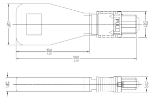
4 Dimension Specifications
5. Fiber Mapping & Polarity
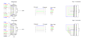
Correct fiber mapping is critical for valid loopback test results. The module routes transmit (TX) lanes back to corresponding receive (RX) lanes through a defined internal fiber path. The mapping must be matched to the target transceiver architecture to produce meaningful diagnostic data.
5.1 Available Polarity Options
5.2 Standard 12-Fiber Active Lane Mapping
In standard 40G-SR4 and 100G-SR4 applications, only 8 of the 12 fibers carry active signals. The remaining 4 fibers (positions 5-8) are physically present but optically inactive. The loopback module maps active lanes as follows:
| Application | TX Lanes (Fiber Position) | RX Lanes (Fiber Position) | Unused Fibers |
| 40G-SR4 (QSFP+) | 1, 2, 3, 4 | 9, 10, 11, 12 | 5, 6, 7, 8 |
| 100G-SR4 (QSFP28) | 1, 2, 3, 4 | 9, 10, 11, 12 | 5, 6, 7, 8 |
| 200G-SR4 (QSFP56) | 1, 2, 3, 4 | 9, 10, 11, 12 | 5, 6, 7, 8 |
| 100G-SR10 (CXP) | 1-10 | 1-10 (loopback all) | 11, 12 |
5.3 Key Position Reference
The MPO-12 connector features a keying notch on the top side and a white dot indicating fiber position 1. When mating with a transceiver (which typically has a male MPO interface with guide pins), the loopback module (female) must be oriented with the key aligned correctly. Incorrect keying can damage the ferrule or produce false test results.
| Orientation | Module Key | Transceiver Key | Mating Condition |
| Type A adapter | Key-Up on module | Key-Down on transceiver | Key-Up to Key-Down (normal mating) |
| Type B adapter | Key-Up on both sides | Key-Up to Key-Up | Flipped orientation for Type B polarity |
Important: Always confirm the internal mapping drawing with the supplier before bulk procurement. An incorrect mapping will produce misleading test results, false failure reports, and wasted troubleshooting time.
6. Transceiver Compatibility
The following table lists verified transceiver form factors and interface types compatible with the 12F OM3 MPO Loopback Module:
| Form Factor | Interface | Data Rate | Compatibility Note |
| SFP+ | Duplex LC | 10 Gbps | Requires MPO-to-LC breakout cable |
| QSFP+ | MPO-12 | 40 Gbps | Direct connection (native) |
| QSFP28 | MPO-12 | 100 Gbps | Direct connection (native) |
| QSFP56 | MPO-12 | 200 Gbps | Direct connection (native, limited reach on OM3) |
| CXP | MPO-12 x2 | 100/120 Gbps | Direct connection on each MPO-12 port |
| CFP2 | MPO-12 | 100 Gbps | Direct connection (native) |
7. Standards & Compliance
| Standard | Description |
| IEC 61754-7 | Fibre optic connectors – MPO connector interface standard |
| IEC 60793-2-10 | Optical fibres – Product specifications – A1a.2 (OM3) |
| TIA-492AAAC | OM3 multimode fiber specification (50/125 um, laser-optimized) |
| TIA-598-C | Optical fiber cable color coding and identification |
| TIA-604-5 | Fiber optic connector intermateability – MPO type |
| ISO/IEC 11801 | Generic cabling for customer premises (OM3 class) |
| IEEE 802.3 | Ethernet standard – multimode reach and link budget definitions |
| IEC 61300-2-x | Basic test procedures: vibration, shock, thermal, humidity |
| IEC 61300-3-4 | Attenuation / insertion loss measurement method |
| IEC 61300-3-35 | Visual inspection of fiber optic connector end-faces |
| UL 94 V-0 | Flammability rating for housing material |
| RoHS 2011/65/EU | Restriction of Hazardous Substances Directive |
| REACH EC 1907/2006 | Registration, Evaluation, Authorisation of Chemicals |
8 Applications
The 12F OM3 MPO Loopback Module is suitable for a wide range of multimode test and verification scenarios in data center, enterprise, and telecommunications environments:
| Application | Description |
| 40G Transceiver Testing | Verify TX/RX functionality and lane balance of 40G-SR4 QSFP+ transceivers without building a full multimode network link |
| 100G Transceiver Testing | Validate 100G-SR4 QSFP28 transceiver port behavior and lane-level diagnostics in multimode environments |
| Switch Port Commissioning | Validate MPO port behavior and signal integrity before live network patching in data center spine-leaf deployments |
| Burn-in / Aging Test | Provide continuous optical loopback for extended equipment reliability and stress testing in factory environments |
| Network Troubleshooting | Isolate equipment-side faults from cabling infrastructure issues during multimode link fault diagnosis and resolution |
| Lab Simulation | Create controlled multimode test paths for parallel optics research, protocol validation, and system-level simulation |
| Factory QA / Acceptance | Support repeatable outgoing inspection and acceptance routines for optical equipment manufacturers |
9. Ordering Information
To place an order or request a quotation, please specify the following parameters:
| Parameter | Options | Default |
| Fiber Count | 12 | 12 |
| Fiber Type | OM3 (50/125 um, laser-optimized multimode) | OM3 |
| Connector Gender | Female (standard), Male (optional) | Female |
| Polish Type | UPC | UPC |
| Polarity | Type A, Type B, Type C, Custom (per drawing) | Type A |
| Performance Grade | Low Loss, Standard | Standard |
| Labeling | Standard or custom label | Standard |
| Packaging | Individual anti-static bag, foam tray, bulk carton | Individual bag |
Part Number Convention: MPO12-LB-OM3-[Gender]-[Polish]-[Polarity]-[Grade]
Example: MPO12-LB-OM3-F-UPC-A-STD = 12F OM3 MPO Loopback, Female, UPC polish, Type A polarity, Standard grade
10. Handling & Maintenance
- Always use the protective dust cap when the module is not mated to prevent end-face contamination.
- Inspect the MPO connector end-face with a fiber inspection microscope (per IEC 61300-3-35) before each insertion. Reject modules with visible scratches, pits, or contamination on the ferrule.
- Clean the connector end-face using an MPO-specific cleaning tool (cassette cleaner, click cleaner, or wet-dry wipe method) before mating if contamination is detected.
- Do not touch the ferrule end-face with bare fingers. Skin oils, lotions, and particulates degrade optical performance and can cause permanent end-face damage.
- Verify the aqua connector shell color matches the target OM3 multimode adapter. Do not mate OM3 connectors with singlemode (yellow/black) adapters or OM1/OM2 (orange/beige) infrastructure.
- Align the keying notch correctly before insertion. Forced insertion with misaligned keys can damage the guide pins and ferrule.
- Store in original anti-static packaging in a clean, dry, temperature-controlled environment (-40 degC to +85 degC).
- Avoid exposure to direct sunlight, high humidity (> 95% RH), and corrosive atmospheres during storage.
- After 500 mating cycles, perform full end-face inspection and re-clean the connector before continued use.